
Sandwich structure and method of making same

a sandwich structure and sandwich technology, applied in the field of sandwich structure and method of making same, can solve the problems of increasing the cost of manufacturing such sandwich structures, the necessity of general use of autoclaves, and the impracticality of using autoclaves, so as to improve the shear, compressive strength, and fatigue strength of sandwich structures. the effect of reducing the cost and impracticality of us

Inactive Publication Date: 2001-09-18
AZTEX
View PDF69 Cites 181 Cited by
  • Summary
  • Abstract
  • Description
  • Claims
  • Application Information

AI Technical Summary

Benefits of technology

It is a further object of this invention to provide such a sandwich structure and method which is extremely versatile.
It is a further object of this invention to provide such a sandwich structure which is significantly less expensive to manufacture than prior art sandwich structures.
It is a further object of this invention to provide such a sandwich structure and method which prevents delamination of the face sheet; from the core material.
It is a further object of this invention to provide such a sandwich structure and method which results in a sandwich structure having improved shear strength, compressive strength, and fatigue strength.
This invention results from the realization that many of the beneficial characteristics of a truss reinforced foam core sandwich structures can be obtained by bending the ends of pins extending from the core over the surfaces of the core and then assembling the face sheets on the core and over the bent over pin ends thus eliminating the expense and impracticability of using an autoclave to drive the pin ends through the face sheets of the sandwich structure.
The pins secure the face sheets to the foam core since the pins extend from one face sheet to the other and their bent over ends become part of the face sheets. In addition, the pins reinforce the foam core and greatly improve the shear, compressive, and fatigue strengths of the sandwich structure.

Problems solved by technology

One potential drawback with these structures is that an autoclave must generally be used to obtain the pressure required to drive the pin ends into the face sheets.
An autoclave adds significantly to the cost of manufacturing such sandwich structures and for large structures the use of an auto-lave may be impractical.

Method used


Image

  • Sandwich structure and method of making same
  • Sandwich structure and method of making same
  • Sandwich structure and method of making same

Examples


Embodiment Construction

Other objects, features and advantages will occur to those skilled in the art from the following description of a preferred embodiment and the accompanying drawings, in which:

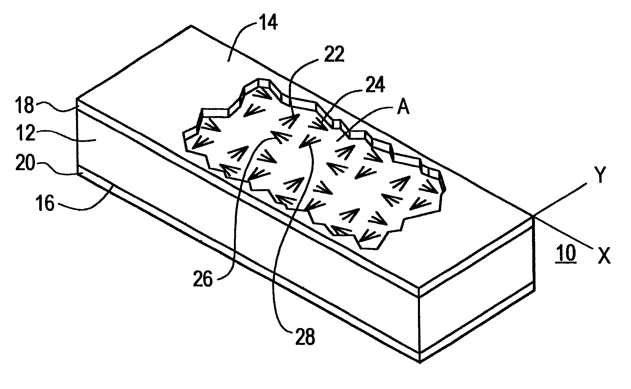
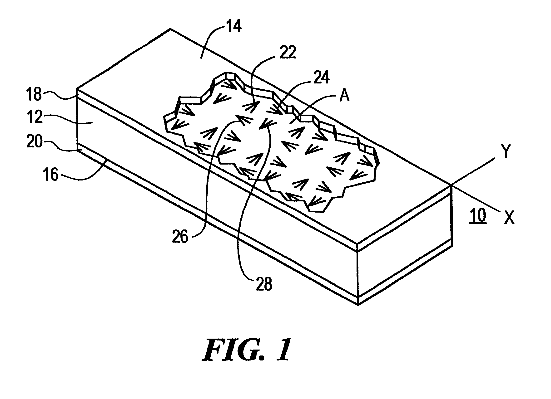
FIG. 1 is a schematic top view of the sandwich structure of the subject invention;

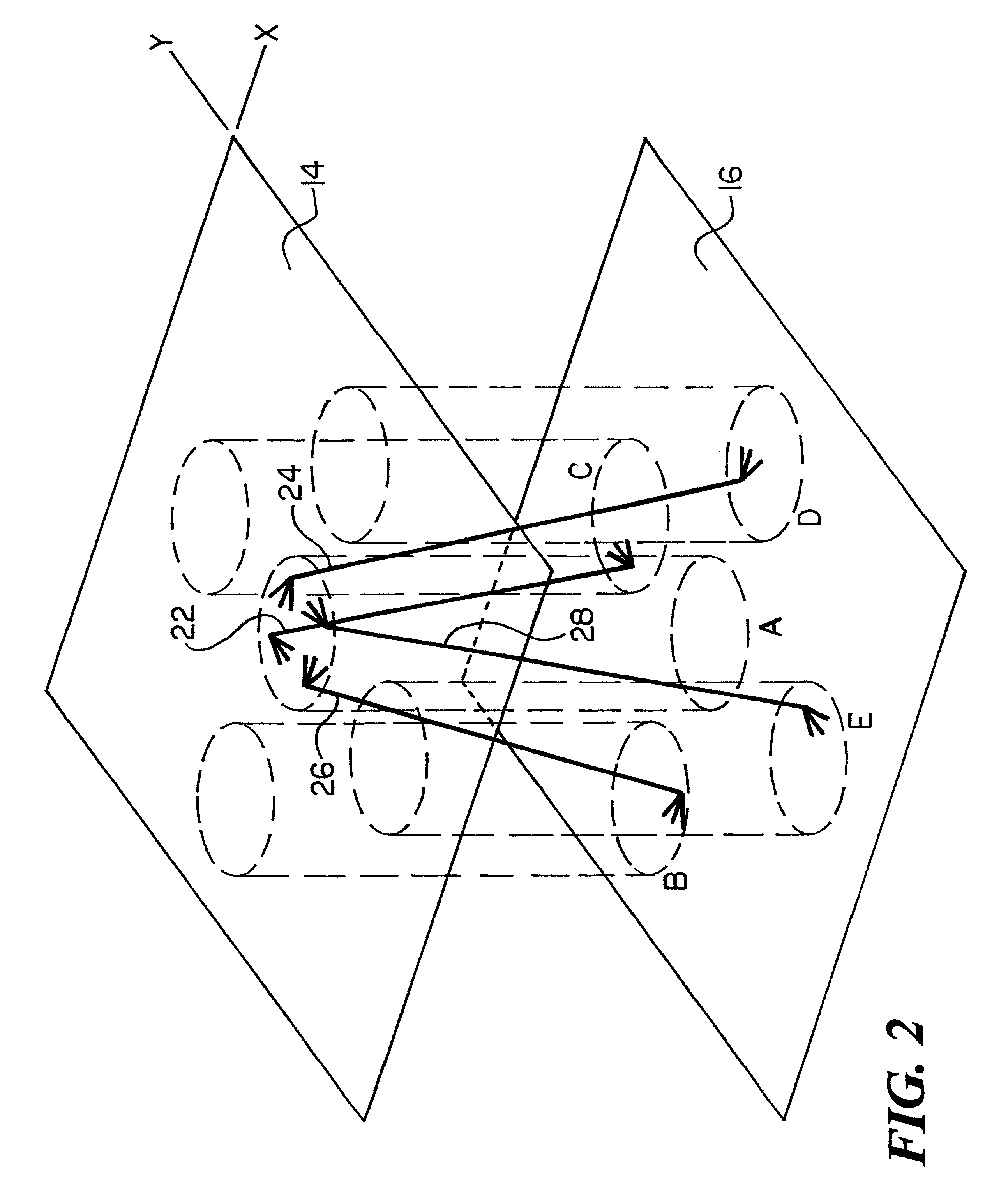
FIG. 2 is a schematic elevational view showing the orientation of the pins in the foam core of the sandwich structure of the subject invention;

FIG. 3 is a simplified three dimensional schematic view showing the pins in the foam core in accordance with the subject invention before their ends are bent over;

FIG. 4 is view similar to FIG. 3 after the pin ends have been bent have over along the top and bottom surfaces of the foam core;

FIG. 5 is a flow chart showing the primary steps associated with manufacturing the sandwich structure of the subject invention;

FIG. 6 is a flow chart depicting the primary steps associated with manufacturing another embodiment of the sandwich structure of the subject invention;

FIG. 7 is a side cross-secti...


PUM

PropertyMeasurementUnit
Angleaaaaaaaaaa
Strengthaaaaaaaaaa

Abstract

A sandwich structure including a core having opposing top and bottom surfaces, a plurality of discrete pins disposed through the core and extending beyond the top and bottom surfaces of the core, a face sheet on the top core surface, and a face sheet on the bottom core surface. The ends of each pin are bent over and lie between the respective core surfaces and the face sheets to secure the face sheets to the core, improve the strength of the core, and to provide a physical connection between the two face sheets. Also disclosed is a reinforced core for a sandwich structure which does not yet have the face sheets assembled to it. Also disclosed is a method of making such a reinforced core and completed sandwich structures including such a core.

Description

This invention relates to a truss reinforced foam core and to such a foam core which can be incorporated as a part of a sandwich structure, the manufacture of which does not require the use of an autoclaveBACKGROUND OF INVENTIONIn U.S. Pat. Nos. 5,624,622 and 5,741,574 incorporated herein by this reference, there are disclosed truss reinforced foam core sandwich structures wherein a plurality of pins are disposed in a foam core and the extending ends of the pins are then driven into composite face sheets on each side of the foam core. See also U.S. Pat. No. 5,736,222 also incorporated herein by this reference.One potential drawback with these structures is that an autoclave must generally be used to obtain the pressure required to drive the pin ends into the face sheets.An autoclave adds significantly to the cost of manufacturing such sandwich structures and for large structures the use of an auto-lave may be impractical.SUMMARY OF INVENTION: IIt is therefore an object of this inven...

Claims


Application Information

Patent Timeline
IPC IPC(8): B32B3/06B32B5/18B32B5/02
CPCB32B3/06B32B5/02B32B5/18Y10T428/24174Y10T428/24008Y10T428/249991Y10T442/651Y10T428/249986B29D99/0021B29C70/24
Inventor KUNKEL, EDWARDBLANEY, ERICMAGEE, CONSTANCERICH, DAVID
Owner AZTEX
Learn More