
Free-space quantum cryptography system

a quantum cryptography and quantum cryptography technology, applied in the field of free-space quantum cryptography system, can solve the problems of unfavorable measurement of x and p, unfavorable standard mathematical encryption algorithm attack, and unfavorable monitoring of transmission system

Inactive Publication Date: 2001-09-11
ILLINOIS INSTITUTE OF TECHNOLOGY
View PDF15 Cites 122 Cited by
  • Summary
  • Abstract
  • Description
  • Claims
  • Application Information

AI Technical Summary

Problems solved by technology

First, any measurements made on a physical system that extracts some information about that system will necessarily disturb that system albeit perhaps only in a minimal way.
At the receiver, the value of either x or p for the physical system is measured; however, due to the uncertainty principle, the measurement of the values of both x and p is precluded.
As computing power increases, standard mathematical encryption algorithms become susceptible to attack.
However, the quantum uncertainty built into the system of this invention is completely unbreakable.
However, if one measures the photon polarization in a basis that is rotated (for example at 45.degree. to the correct basis), then the precise bit value cannot be determined.
A measurement on the polarization state of the photon will destroy information on the input polarization state as a result of which any attempt to eavesdrop on the system will perturb the system in a detectable manner.
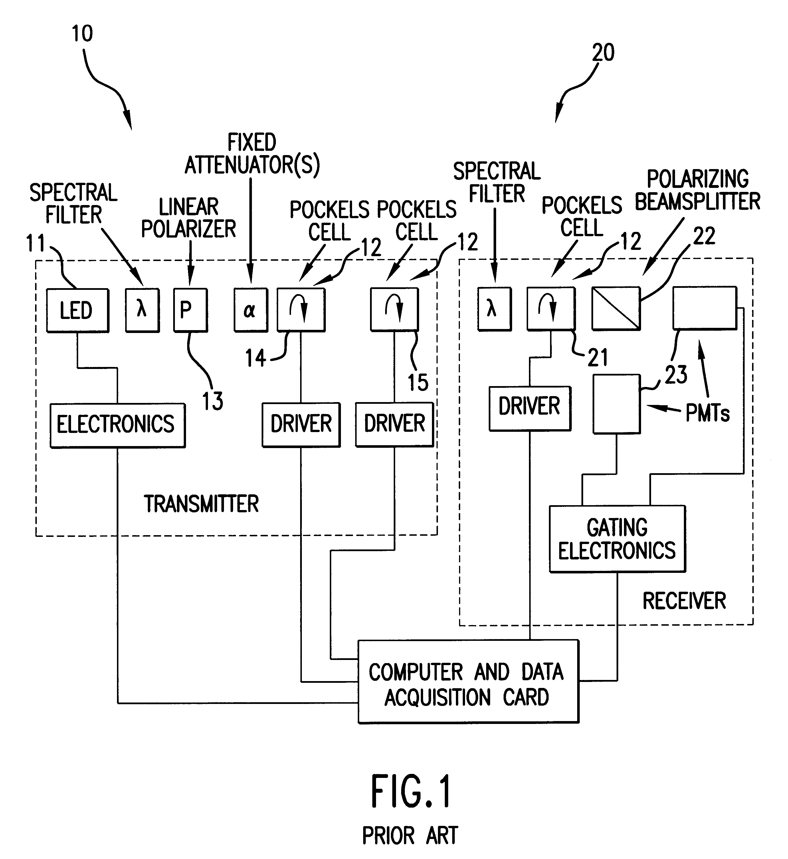
This conventional system suffers from several drawbacks.
First, the maximum data rate is limited by the switching speed of the Pockels cells 12, which is typically 1 Mb / s.
Secondly, the Pockels cells phase retardation (and, thus, polarization control) is highly temperature dependent, drifting significantly with environmental changes.
Thirdly, the Pockels cells and their driver electronics are quite expensive, with prices for a single unit near $3,500.
Thus, any interception of the photon will destroy the correlation.

Method used


Image

  • Free-space quantum cryptography system
  • Free-space quantum cryptography system
  • Free-space quantum cryptography system

Examples


Embodiment Construction

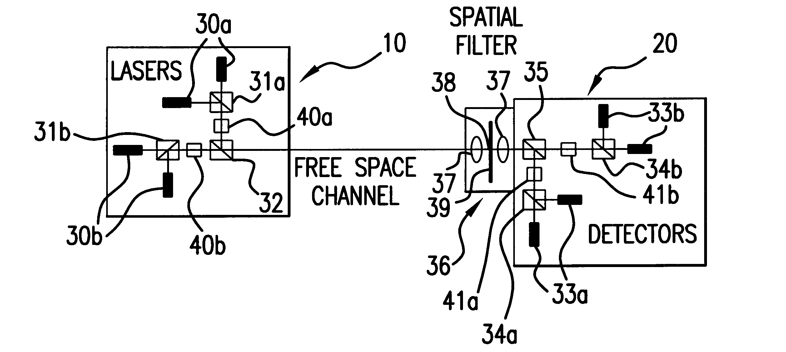
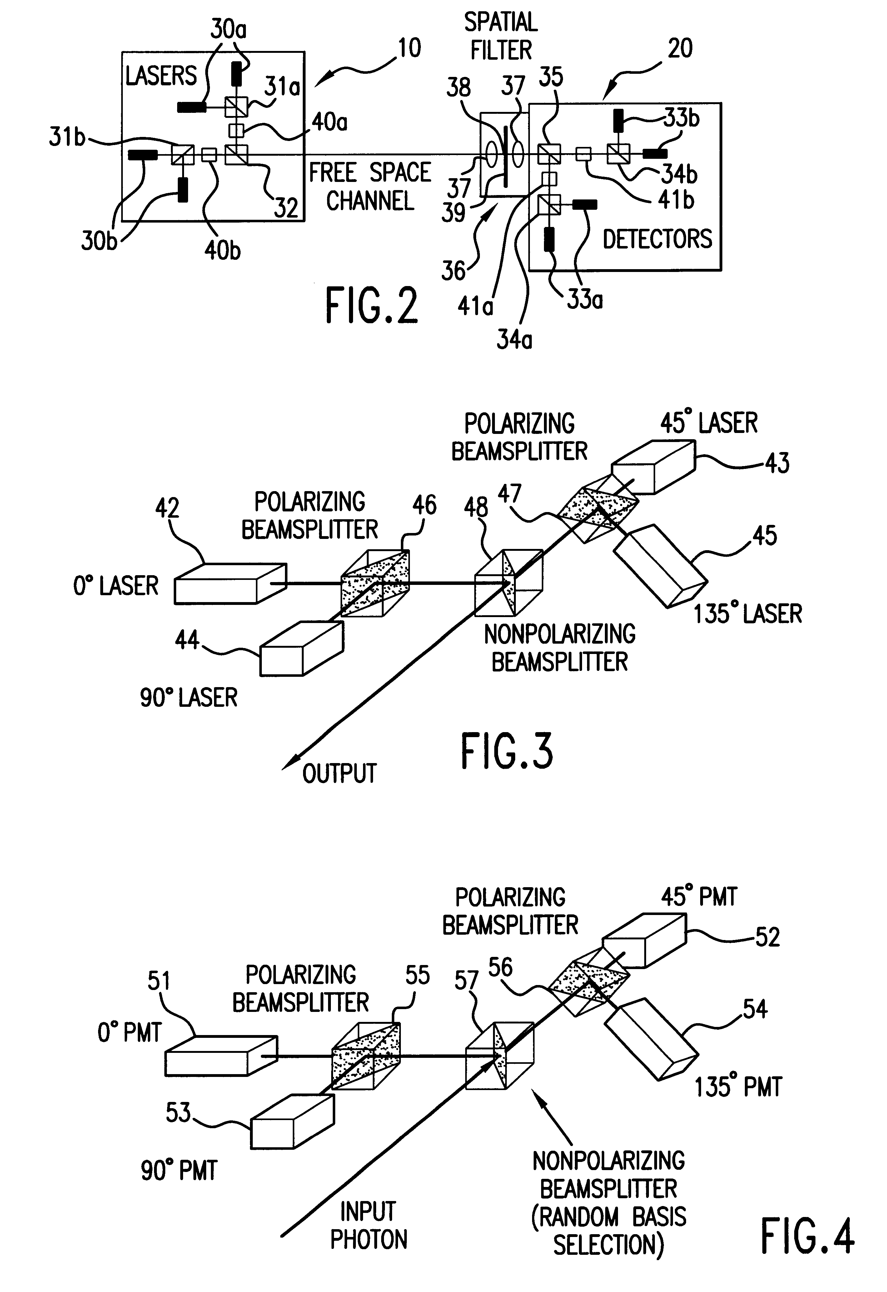
FIG. 2 is a schematic diagram of a system for quantum key delivery in a single-photon, free-space cryptography scheme in accordance with one embodiment of this invention. The system comprises a transmitter 10 and a receiver 20 in communication with each other through a free-space channel. Disposed within the free-space channel is a spatial filter 36 comprising a combination of lenses 37 and a small pinhole 38, thereby providing highly accurate angular resolution at receiver 20. As previously stated, this fine resolution decreases the ambient light levels by 8-10 orders of magnitude and makes daylight operation possible. It will be apparent to those skilled in the art that operation of the system of this invention without a spatial filter is feasible if one is willing and able to operate under low light or darkness conditions.

Transmitter 10 comprises two pairs of photon sources 30a and 30b, in the embodiment shown in the form of lasers, each said photon source representing a specific...


PUM


Abstract

A system and method for quantum key delivery in a single-photon, free-space cryptography scheme including a transmitter and a receiver. The transmitter includes two pairs of photon sources, each of which represents a specific photon polarization direction. The first pair of photon sources represents a first polarization basis while the remaining pair of photon sources represents a second polarization basis. The first and second polarization basis are rotated with respect to each other so as to produce non-orthogonal polarization eigenstates. A transmitter polarizing beamsplitter corresponding to each of the pairs of the photon sources is provided whereby the polarizations of each of the photon sources of each pair of photon sources are recombined. A transmitter non-polarizing beamsplitter is provided whereby the recombined polarizations are combined for output to the receiver. The receiver includes a set of optics inversely disposed with respect to the optics of the transmitter and two pairs of photon detectors.

Description

1. Field of the InventionThis invention relates to a system and method for key delivery using quantum cryptography. The system allows for delivery of single photons from a transmitter to a receiver, with information contained in the polarization states of the photons. The system eliminates expensive, unstable, complicated components, called Pockels cells, used in prior designs and replaces them with less expensive passive components and additional optical sources. Benefits arising from use of the system of this invention include system speed, stability and simplicity. In addition, the receiver design permits single photon operation in daylight conditions.2. Description of Prior ArtGenerally, quantum cryptography is a system which enables two parties to communicate in secret with the security of the communication being guaranteed by the laws of quantum physics. More particularly, a quantum cryptography system is a key distribution system that attempts to link the security of the syst...

Claims


Application Information

Patent Timeline
IPC IPC(8): H04L9/08
CPCH04L9/0858
Inventor PATTERSON, DAVID B.KUBIK, JAMES M.
Owner ILLINOIS INSTITUTE OF TECHNOLOGY
Learn More