Cube corner cavity based retroreflectors and methods for making same

a retroreflector and cube corner technology, applied in the field of cube corner cavity retroreflectors, can solve the problems of inconvenient retroreflector manufacturing, inconvenient retroreflector manufacturing, and inability to meet the requirements of the application, and achieve the effects of low or no oxidation, efficient retroreflection of incident light, and high specular reflectivity

Inactive Publication Date: 2001-09-11
3M INNOVATIVE PROPERTIES CO
View PDF43 Cites 83 Cited by
  • Summary
  • Abstract
  • Description
  • Claims
  • Application Information

AI Technical Summary

Benefits of technology

According to one aspect of the invention, retroreflective cube corner sheeting is provided with a body layer that has a structured surface comprising recessed faces and top surfaces, the recessed faces forming cube corner cavities. The recessed faces have a high specular reflectivity to permit efficient retroreflection of incident light. However, the top surfaces have a low or otherwise reduced specular reflectivity so as to provide desired optical or mechanical properties. A film of reflective material is disposed at least on the recessed faces to provide the high specular reflectivity. The film can be continuous over the structured surface, covering both the recessed faces and the top surfaces, or can be discontinuous, covering only the recessed faces and being substantially absent from the top surfaces. In several disclosed embodiments, the film is selectively exposed on the recessed faces. The top surfaces of the structured surface preferably comprise flat areas that are diffusely reflective, contributing to the whiteness of the sheeting, and that circumscribe an integral number of cube corner cavities. The diffuse reflectivity of the top surfaces can be provided by the body layer material itself, by a separate layer such as paint, or by a non-smooth surface finish. A cover layer can also be provided to protect the cube corner cavities from contamination and for improved weatherability.

Problems solved by technology

Each of these techniques has its own benefits and limitations.
Gray-cast is disadvantageous in signing applications because of its effect on perceived color of the sign, most notably the reduction of daytime whiteness.
A second drawback is corrosion or other degradation of the reflective film.
Unfortunately, silver is more susceptible to degradation than is aluminum.
Although a cover layer can provide a certain amount of protection, harmful agents present at exposed edges of the sheeting can migrate along the reflective film, steadily advancing into the sheeting starting from such edges.

Method used


Image

  • Cube corner cavity based retroreflectors and methods for making same
  • Cube corner cavity based retroreflectors and methods for making same
  • Cube corner cavity based retroreflectors and methods for making same

Examples


examples 1-4

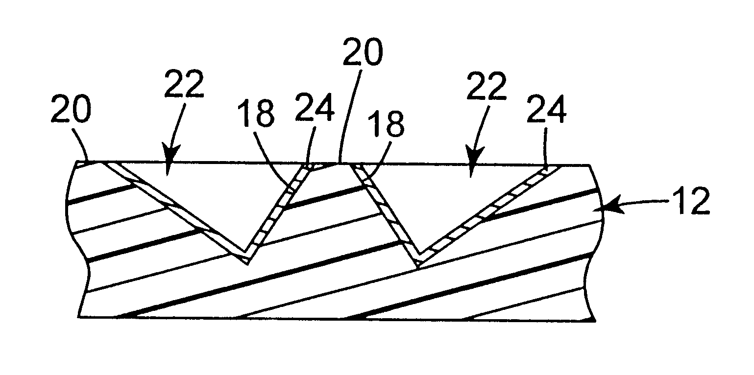
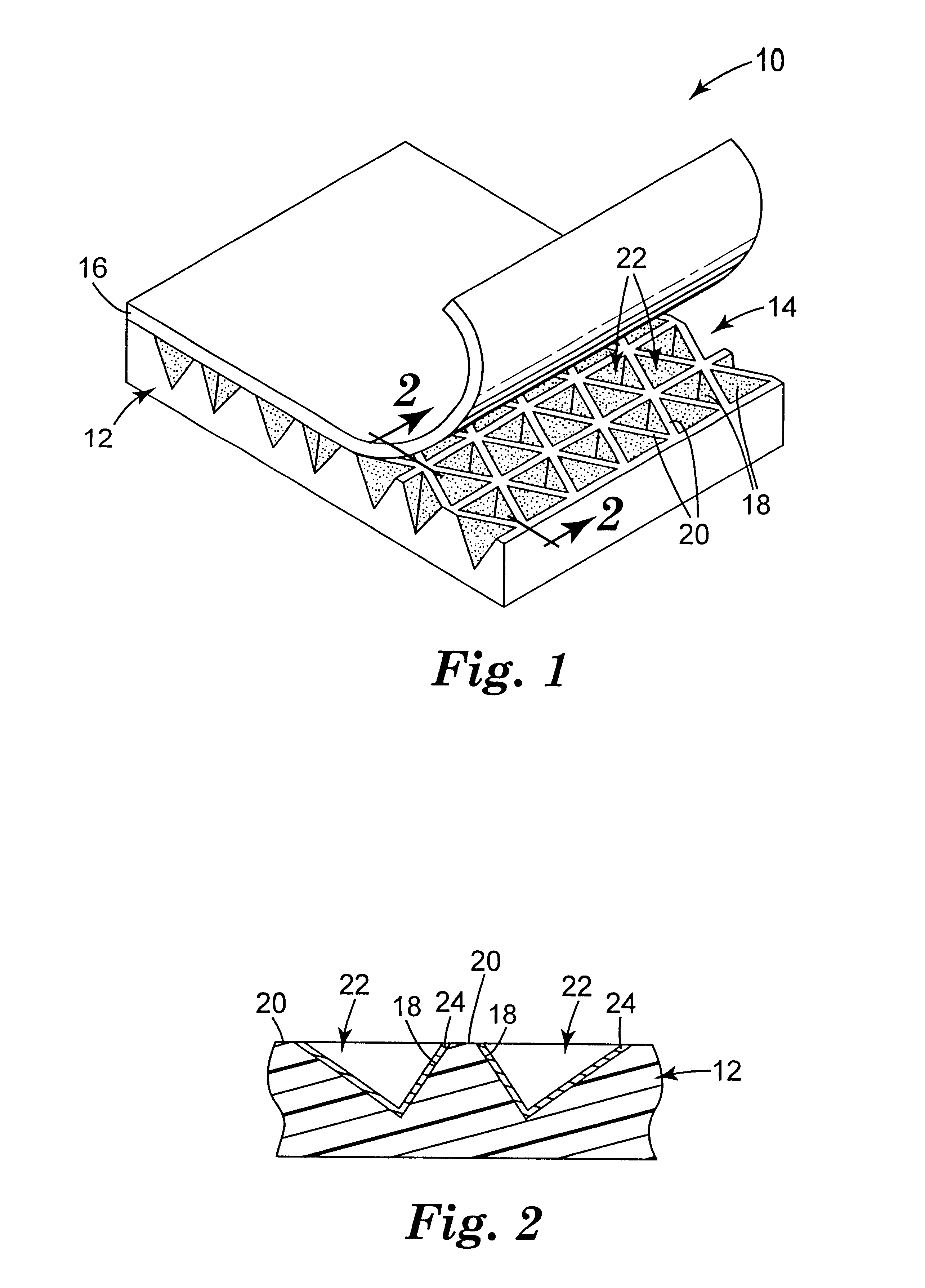
Four body layers were embossed with a mold to impart a structured surface similar to that shown in FIG. 1. The mold had a structured surface consisting of three sets of flat-bottomed grooves, and was the negative replica of a prior mold whose upper portions had been ground down flat with an abrasive. The embossed body layers were made of polycarbonate. The body layers for Examples 1 and 2 had a thickness of about 43 mils (1.1 mm) and included sufficient TiO.sub.2 filler to make them opaque with a diffuse white surface appearance. Those for Examples 3 and 4 had a thickness of about 18 mils (0.46 mm) and included instead a red dye to give a diffuse red surface appearance. The structured surface of each body layer consisted essentially of three intersecting sets of parallel ridges. Two of the sets, refered to as "secondary" ridge sets, had uniform ridge spacings of about 16 mils (408 .mu.m) and intersected each other at an included angle of about 70 degrees. The other set of parallel r...

examples 5-8

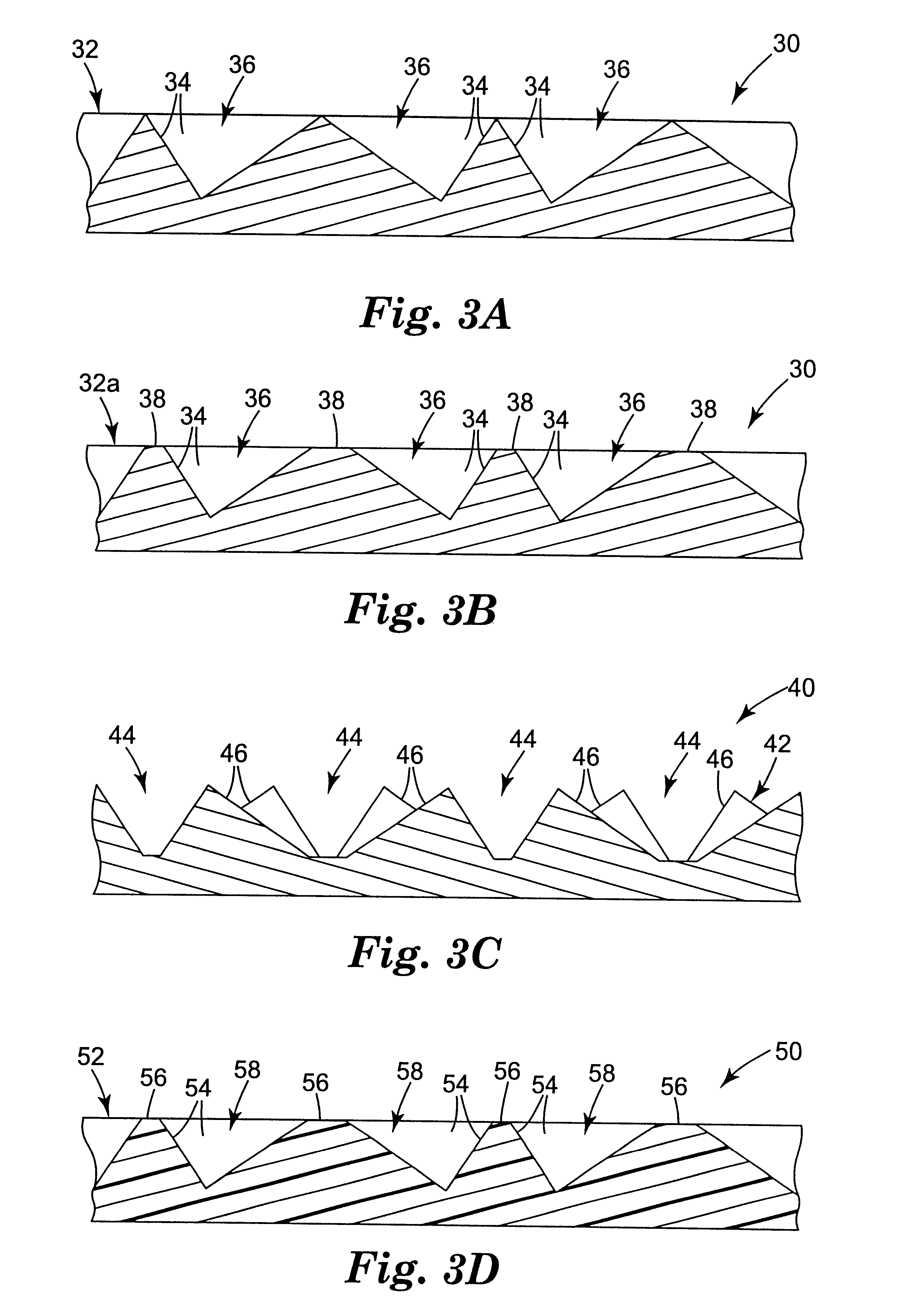
Samples were made to better quantify the roughening concept. Four polycarbonate body layers were made having a structured surface similar to that of FIG. 1 with three intersecting sets of parallel ridges, each ridge set having a uniform spacing of about 8.5 mils (216 .mu.m) and each set intersecting the other two sets at 60 degrees, thus forming non-canted cube corner cavities. Each ridge had a flat top surface about 1.65 mils (42 .mu.m) in transverse dimension, so that the top surfaces took up about 50% of the structured surface area in plan view. A flat-tipped diamond tool had been used to form the master mold from which the body layers were replicated, and as a result the top surfaces were initially optically smooth. The top surfaces of the samples were then selectively roughened by lightly rubbing the structured surface side of the body layer with different abrasives. Thereafter, the modified structured surfaces were vacuum coated with a continuous aluminum vapor coat about 100 ...


PUM

PropertyMeasurementUnit
aperture sizeaaaaaaaaaa

Abstract

Retroreflective sheeting includes a body layer having a structured surface with recessed faces and top surfaces, the recessed faces forming cube corner cavities. The recessed faces have a high specular reflectivity, while the top surfaces have a low specular reflectivity. In some embodiments a substantially continuous film of reflective material covers the structured surface, and a masking substance is provided over the reflective material at the top surfaces. Alternatively, the top surfaces are given a non-smooth surface finish so that the film of reflective material on those portions has a diffuse reflectivity. In other embodiments the film of reflective material is discontinuous, disposed selectively on the recessed faces and not on the top surfaces. A cover layer is also provided, and can bond at least to the top surfaces. Keeping the top surfaces substantially free of reflective material inhibits corrosion and can enhance the bond integrity. The top surfaces are preferably flat, and diffusely reflective to enhance the daytime whiteness of the sheeting.

Description

The present invention relates generally to retroreflective articles such as sheeting. More particularly, the invention relates to such articles or sheetings in which retroreflective elements comprise reflective faces arranged to form a cavity.The reader is directed to the glossary at the end of the specification for guidance on the meaning of certain terms used herein.Cube corner retroreflective sheetings can generally be categorized as those that use a rear-surface body layer and those that use a front-surface body layer. Commercially available cube corner retroreflective sheetings are of the former type, in which a thin transparent body layer has a substantially planar front surface and a rear structured surface comprising a plurality of geometric structures of pyramidal shape, some or all of which include three reflective faces configured as a cube corner element. Light is incident on the planar front surface, passes through the thickness of the body layer, and is retroreflected ...

Claims


Application Information

Patent Timeline
Patent Type & Authority Patents(United States)
IPC IPC(8): G02B5/124G02B5/12G02B5/02G02B5/08
CPCG02B5/124Y10T428/24917Y10T428/24521Y10T428/31Y10T428/24612Y10T428/24479Y10T428/24545Y10T428/24942Y10T428/24413Y10T428/24851Y10T428/24529
Inventor BENSON, GERALD M.SMITH, KENNETH L.CODERRE, JAMES C.
Owner 3M INNOVATIVE PROPERTIES CO
Why Eureka
Try Eureka