
Bar code scanning system and method

Inactive Publication Date: 2001-07-31
SICK AUTO IDENT +1
View PDF20 Cites 20 Cited by
  • Summary
  • Abstract
  • Description
  • Claims
  • Application Information

AI Technical Summary

Benefits of technology

It is therefore an object of this invention to provide a scanning system and method which improves accuracy while reducing cost and maintenance requirements.
It is a further object of this invention to provide such a system and method which reduces processor loading while improving performance.
It is a further object of this invention to provide such a system and method which enables high-precision bar code reconstruction through the use of standard-precision optical components.
It is a further object of this invention to provide such a system and method which enables accurate bar code reconstruction without requiring multiple passes through the leading edge of the bar code.

Problems solved by technology

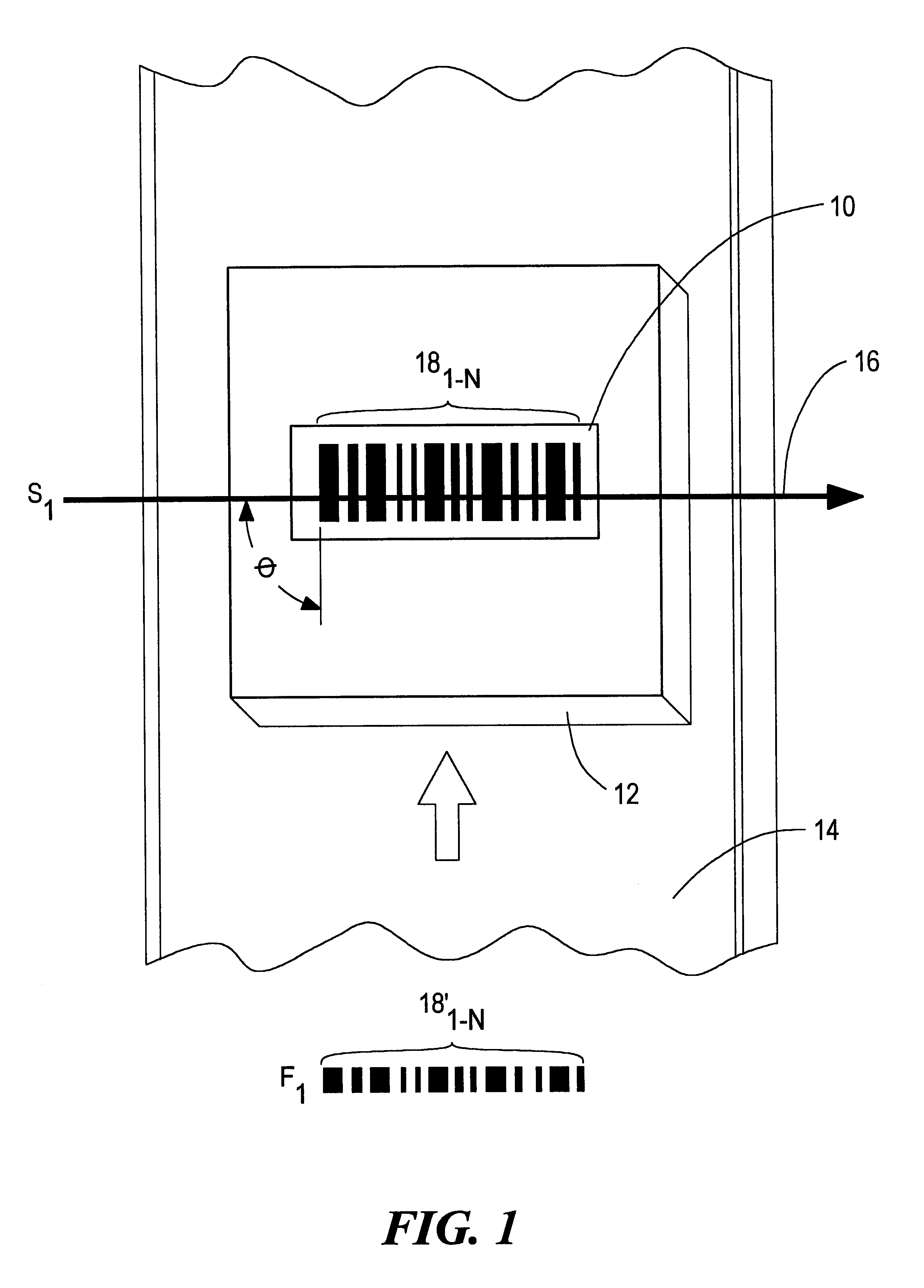
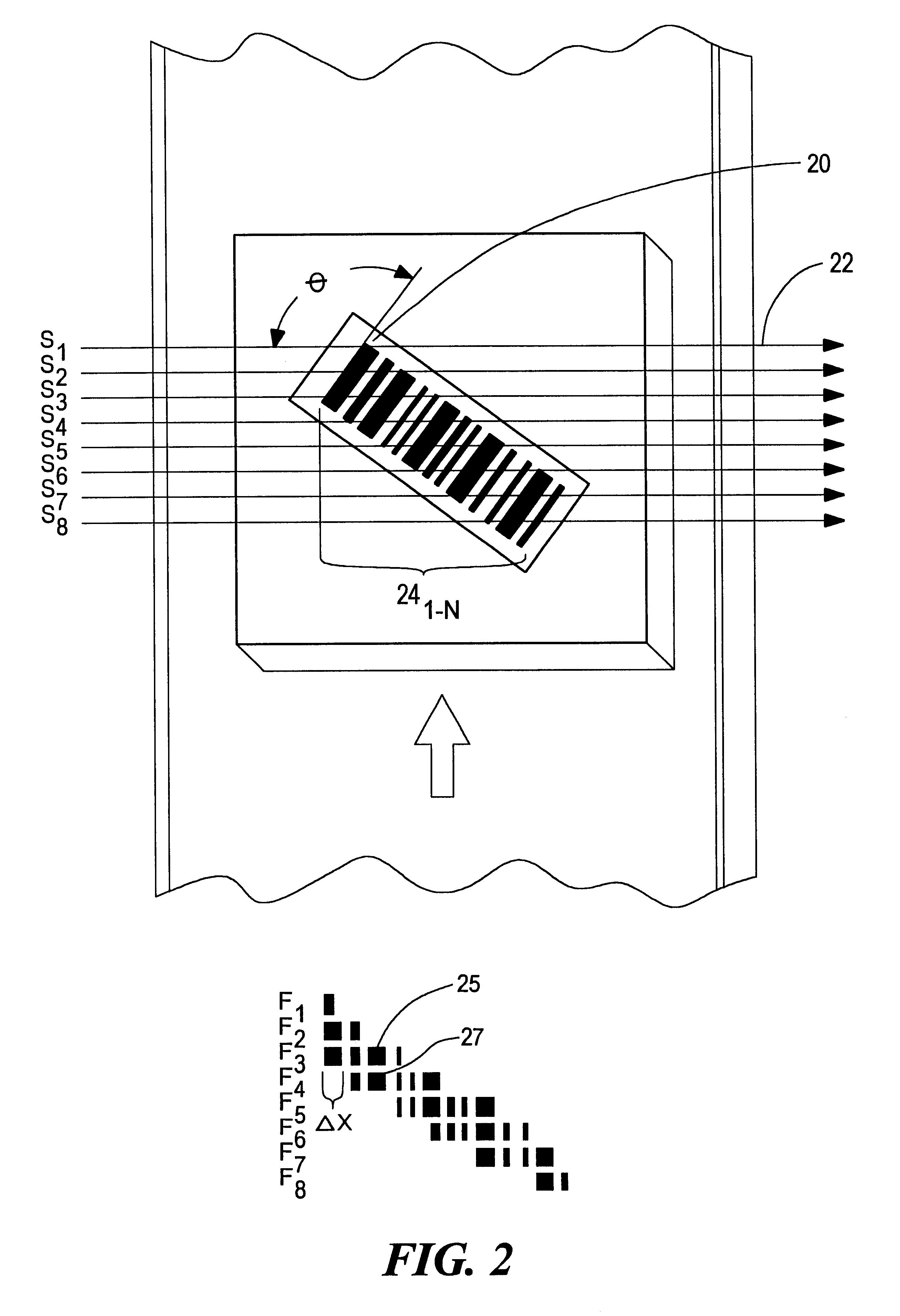
If the bar code is positioned at any angle, other than a right angle, to the path of the scanning laser beam, the entire bar code may not be scanned in one sweep, resulting in an incomplete scan and a bar code fragment being retrieved.
There are several problems associated with this method, all which originate from the fact that successive fragments are repeatedly shifted until they are in alignment with the previous fragment.
This approach to aligning fragments requires considerable processor power, resulting in CPU loading and slow performance.
This situation is only exacerbated when the scan length, or data string length, is considerably long resulting in a high number of shifts required to align each successive fragment.
Since this method utilizes the same repeated shifting alignment method, it suffers from the same shortcomings as the previous method (high CPU utilization and low performance).
Again, this system suffers from the same problems (high CPU utilization and low performance) that afflict the previously-described methods.
This results in the system being prohibitively expensive and requiring a high level of maintenance to ensure that such precise tolerances are maintained.
Therefore, any inaccuracy in the data retrieved from the individual data elements within each fragment Will result in a misalignment of the scan fragments.
There are several problems associated with this method, including those of the previous method e.g. requiring extremely precise components, relying on the content of the bar code label to align subsequent scans.
Additionally, since the scanning beam tends to move at a very high rate of speed, this device is subject to inaccuracies resulting from an increased depth of field.
Therefore, the accuracy of the offset determined by shifting the first two scan fragments into alignment is further diminished.
Specifically, as the depth of field increases, the accuracy of the optics and electrical components utilized in a system employing this method must increase accordingly, a difficult task when considering the precise level of the components required for a normal depth of field.

Method used


Image

  • Bar code scanning system and method
  • Bar code scanning system and method
  • Bar code scanning system and method

Examples


Embodiment Construction

Other objects, features and advantages will occur to those skilled in the art from the following description of a preferred embodiment and the accompanying drawings, in which:

FIG. 1 is a plan view of a bar code being scanned perpendicular to its bars and spaces;

FIG. 2 is a plan view of a bar code being scanned at an angle not perpendicular to its bars and spaces;

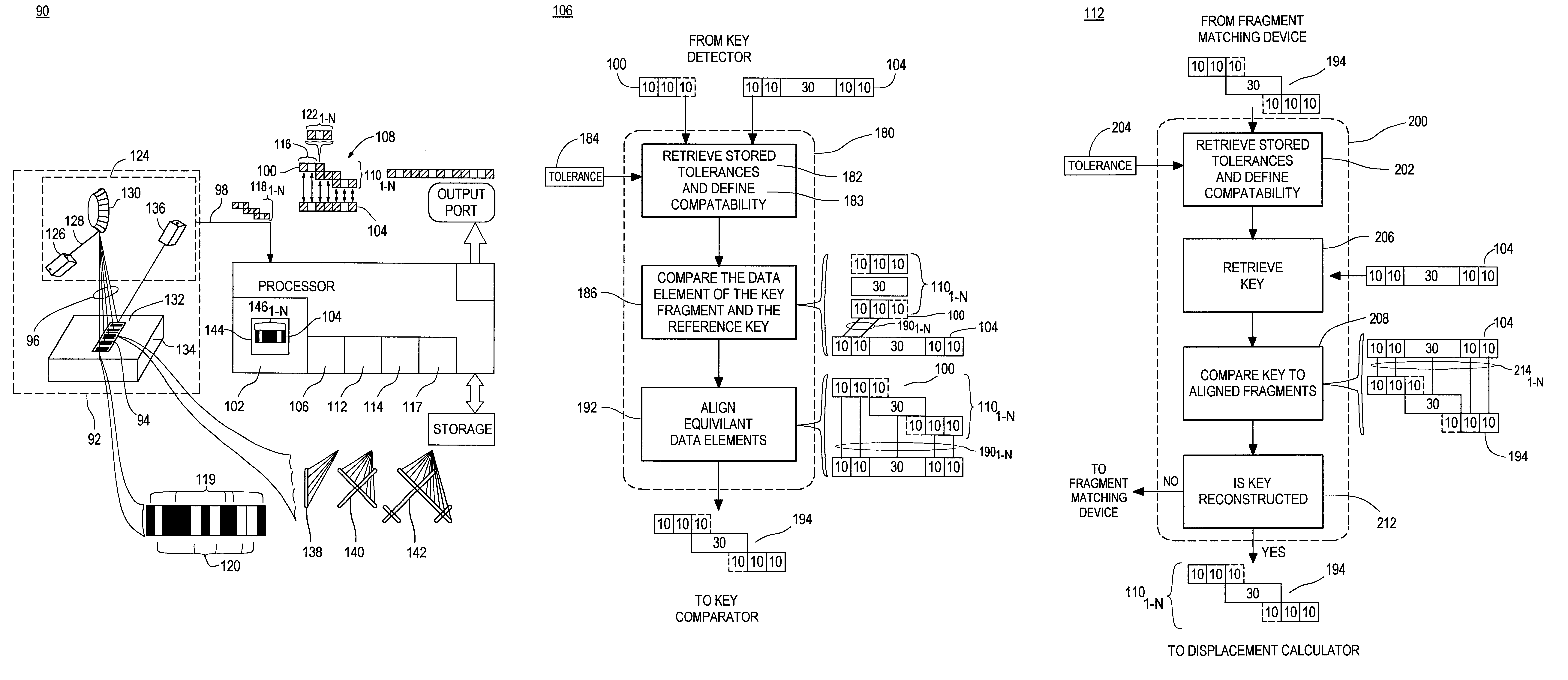
FIG. 3 is a diagrammatic view of a bar code scanning system according to this invention;

FIG. 4A is a plan view of a bar code reference key being scanned at an angle not perpendicular to its bars and spaces and the scan fragment and plurality of data elements produced by each scan sweep according to this invention;

FIG. 4B is a plan view of a reconstructed key produced by the aligning of the scan fragments of FIG. 4A with the reference key;

FIG. 5 is a more detailed view of one embodiment of this invention using a microprocessor;

FIG. 6 is a block diagram of the key detector of this invention;

FIG. 7 is a block diagram of a fragm...


PUM


Abstract

A bar code scanning system and method for scanning a bar code containing a key including successively scanning the bar code and providing, for each scan, a plurality of data elements forming a scan fragment for at least a portion of the bar code, identifying each fragment containing a portion of a reference key, detecting when there has been a match between a reference key and the identified key fragments, determining if a complete key has been constructed from the key fragments, calculating a displacement between the key fragments which constructed the complete key, and aligning data fragments of the bar code by placing each successive data fragment in alignment with the previous data fragment offset by the amount of the displacement.

Description

This invention relates to a bar code scanning system and method and more particularly to one which repeatedly scans a bar code and compares the data scanned with a predetermined key to establish a displacement which enables accurate reconstruction of the entire bar code from individual scan fragments.BACKGROUND OF INVENTIONOptical scanning systems are used throughout industry for many applications. One such application is bar code scanning and decoding. Bar code symbols are printed on many products and packages today allowing for high speed, accurate and efficient routing of the parcels throughout packaging, shipping and sorting facilities. These bar codes are either printed on the outside of the package in an easily visible location or printed on a label affixed to the outside of the package so that they can be scanned by bar code readers and scanning devices.Often, these bar code scanning devices are mounted above a conveyor belt and the packages being scanned are placed on a conv...

Claims


Application Information

Patent Timeline
IPC IPC(8): G06K7/14
CPCG06K7/14
Inventor DWINELL, JOHN F.LYDON, RICHARD
Owner SICK AUTO IDENT
Learn More