Pressure pulse generator for measurement-while-drilling systems which produces high signal strength and exhibits high resistance to jamming
- Summary
- Abstract
- Description
- Claims
- Application Information
AI Technical Summary
Benefits of technology
Problems solved by technology
Method used
Image
Examples
Embodiment Construction
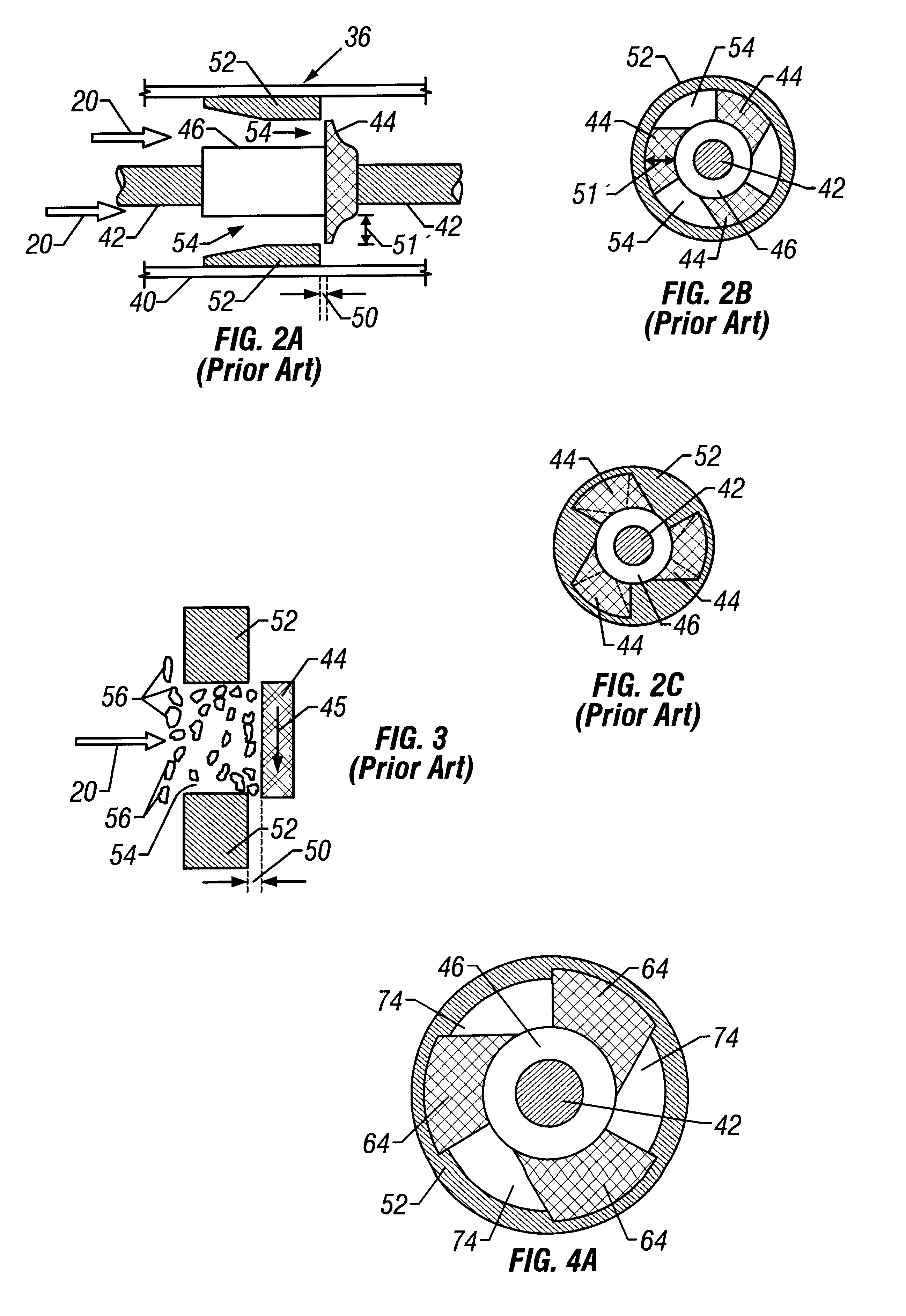
FIGS. 8a-8c illustrate the preferred embodiment of the invention. Similar operational principles as previously detailed also apply to this preferred embodiment. FIG. 8a is a view of a rotor 144 and stator assembly, as seen perpendicular to the shaft 42. The radius of each blade of the rotor 144 is defined as r.sub.1 and is measured from the center line axis of the shaft 42 to the outer perimeter of the rotor. The position of the rotor 144 with respect to stator orifices 154 within the body 152 is such that the orifices are completely open. The radius of each stator orifice 154 is defined as r.sub.2 and is measured from the center line axis of the shaft 42 to the outer perimeter of the orifice. FIG. 8b illustrates the rotor-stator assembly in the fully closed position, leaving closed flow orifices 170 through which drilling fluid and suspended particles can flow. Labyrinth seals 51 are again employed between the rotor 144 and the stator body 152. The closed flow orifice, or minimum p...
PUM
 Abstract
Description
Claims
Application Information
 - R&D
- Intellectual Property
- Life Sciences
- Materials
- Tech Scout
- Unparalleled Data Quality
- Higher Quality Content
- 60% Fewer Hallucinations
Browse by: Latest US Patents, China's latest patents, Technical Efficacy Thesaurus, Application Domain, Technology Topic, Popular Technical Reports.
© 2025 PatSnap. All rights reserved.Legal|Privacy policy|Modern Slavery Act Transparency Statement|Sitemap|About US| Contact US: help@patsnap.com


