Molded surface fastener, and molding method and molding apparatus of the same

Inactive Publication Date: 2001-04-03
YKK CORP
View PDF14 Cites 123 Cited by
  • Summary
  • Abstract
  • Description
  • Claims
  • Application Information

AI Technical Summary

Benefits of technology

to provide a molded surface fastener which can be continuously molded by an entirely new molding mechanism and which has engaging elements molded to have new shapes which are not conventional and of various sizes so that maintenance and management can be easy to achieve and a productivity is high. It is also an object of the invention to provide a molding process and a molding apparatus of the molded surface fastener.
Vibration speed may be changed at random. In this case, the shapes of the engaging elements arranged in the molding direction can be changed in the same direction. Also, at least one or more lines of a plurality of engaging-element-molding portions in a lateral direction perpendicular to the molding direction may be provided with a height and a shape different from those of the lines of the other engaging-element-molding portions. In this case, the plurality of molded engaging elements arranged in a width direction of the substrate surface have different heights or shapes. By changing the heights or shapes, it is possible to appropriately adjust the engaging strength, the engaging rate, the peeling strength, and the like.

Problems solved by technology

According to the above molding methods, the shape or the size of the engaging elements is limited, if their productivity is high, while a continuous molding is difficult to achieve or a number of processes increases so that the productivity is decreased, if the shape or the size of the engaging elements is optional to some extent.
Specifically, a high processing accuracy is required especially to cut the ribs, so that maintenance and management for this purpose requires considerable workload and time.
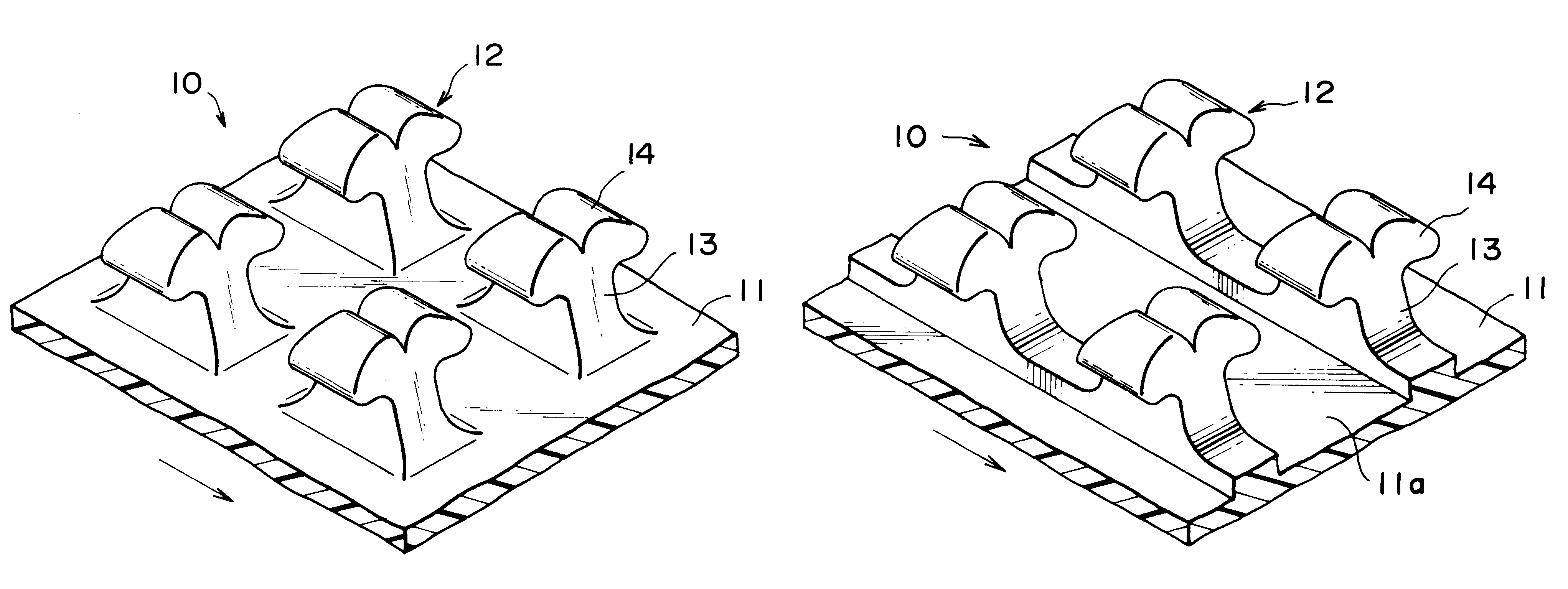
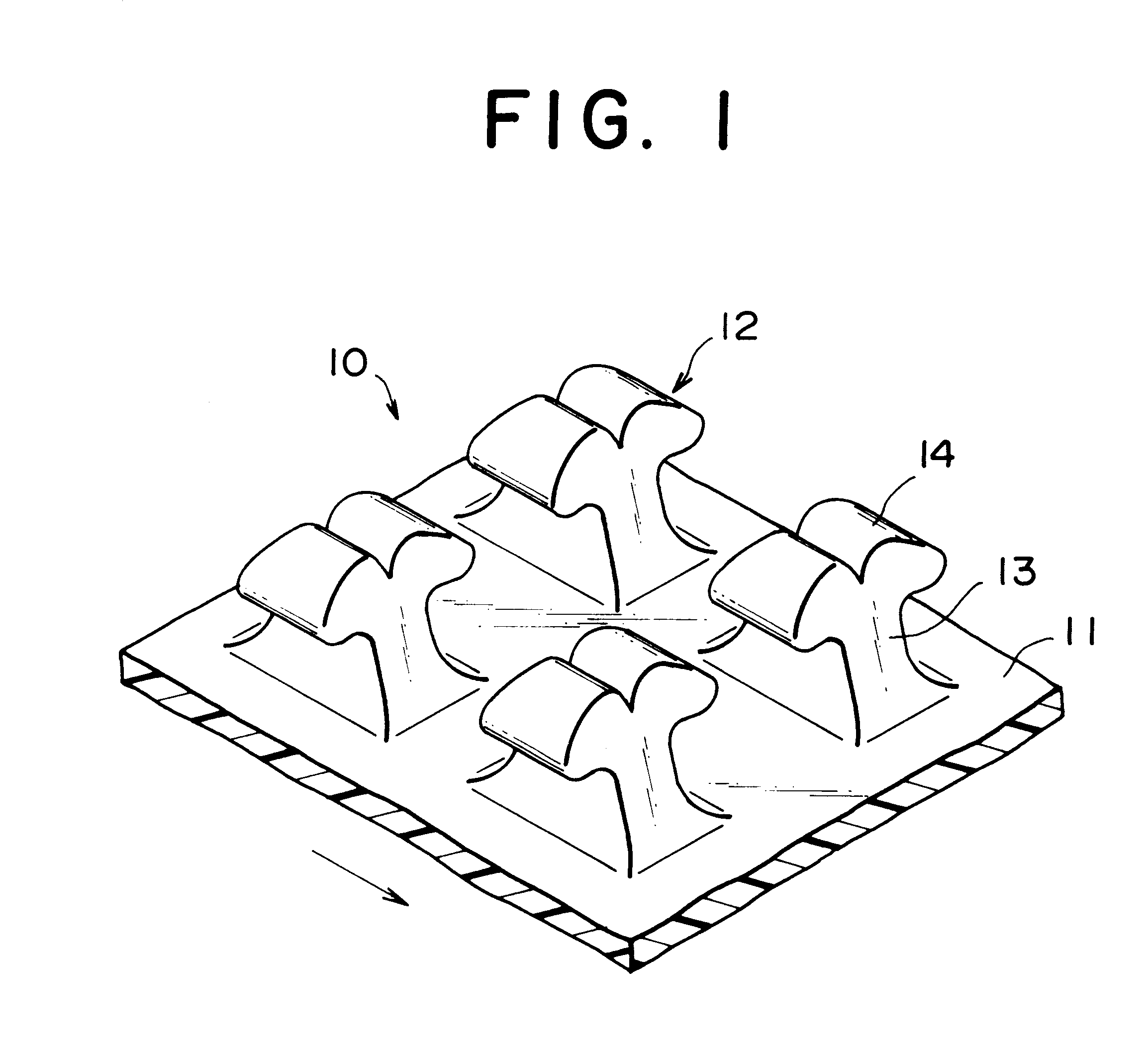
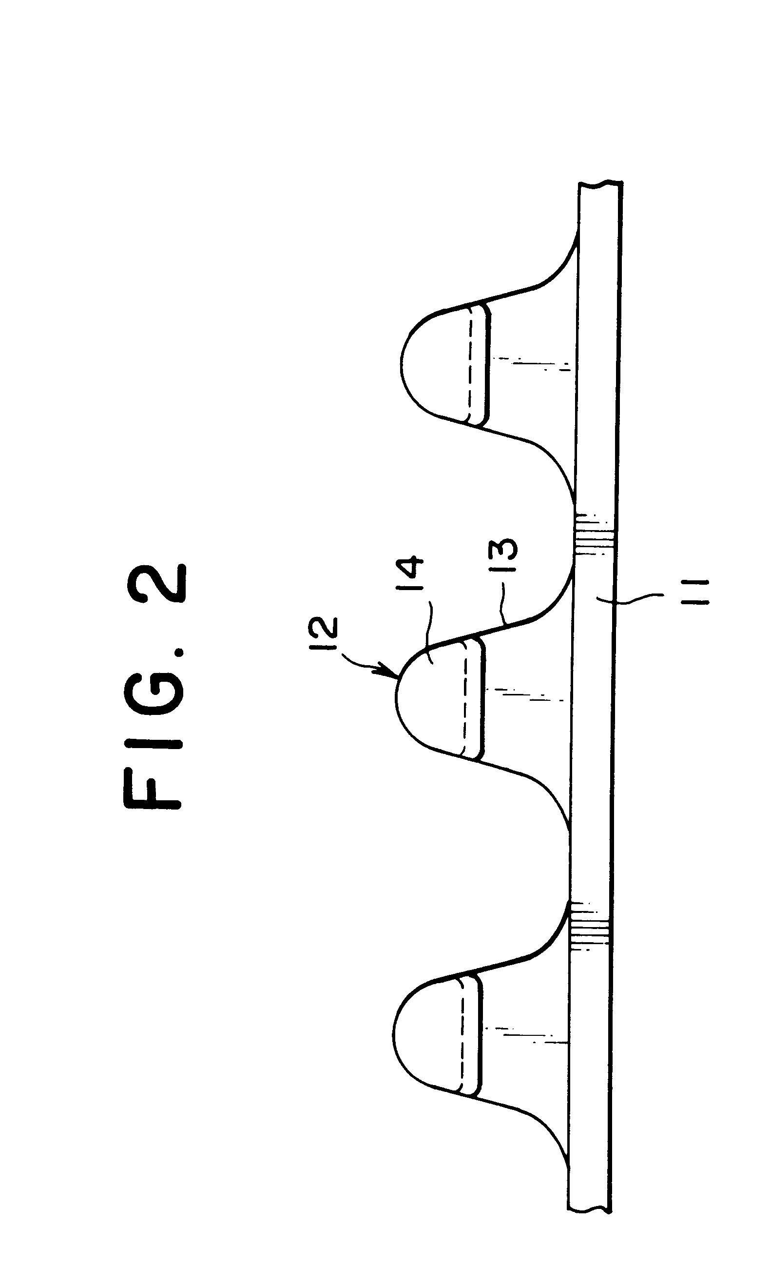
Further, the engaged companion loop is not easily detached due to a gouged shape of a neck portion of the engaging element which is a boundary between the engaging head and the stem thereof, as compared with the conventional molded surface fastener wherein the width of the engaging head is constant in the direction, thereby increasing an engaging rate, an engaging force, and a peeling force.
With this shape, in addition to the above-described functions and effects, even if the engaged companion loops are pulled upward, the loops are not easily detached from the engaging heads, thereby further increasing the engaging force as compared with a case where the engaging heads linearly project from the stems.
Because a plurality of manufacturing processes are required, the conventional extrusion molding is not efficient.

Method used


Image

  • Molded surface fastener, and molding method and molding apparatus of the same
  • Molded surface fastener, and molding method and molding apparatus of the same
  • Molded surface fastener, and molding method and molding apparatus of the same

Examples


first embodiment

The surface fastener with the above structures are efficiently produced by a molding apparatus 100 of the present invention shown in FIG. 7. FIG. 7 shows the molding apparatus according to the present invention. In the molding apparatus of this type, because it is not largely different from a conventional structure, the extruder is not illustrated in FIG. 7 and its specific description is omitted here. In FIG. 7, a reference numeral 101 designates an extruding nozzle mounted to the extruder (not shown) and the extruding nozzle 101 has an extruding hole 102 communicating with an inside resin channel. A front end portion of the extruding nozzle 101 has a vertical face 101a and a horizontal face 101b horizontally extending forward from the vertical face 101a. The extruding hole 102 has a laterally long and narrow substrate-molding portion 102b along a lower end of the vertical face 101a for molding the flat substrate 11. Engaging-element-molding portions 102a for molding the engaging e...

second embodiment

FIG. 9 shows the molding apparatus of the molded surface fastener according to the present invention. FIG. 10 is a fragmentary perspective view of a portion of the surface fastener showing an example of arrangement of the engaging elements 12 molded by the molding apparatus.

As shown in FIG. 9, the present embodiment comprises an extruding nozzle 111 having a similar structure to that of the above first embodiment, a front and rear pair of first and second ascending / descending member 113, 114 disposed in front of the extruding nozzle 111, and crank mechanisms 117 and 118 which are connected through links 115 and 116 to the ascending / descending members 113 and 114, respectively, and ascend and descend the first and second ascending / descending members 113 and 114. Other structures are similar to those in the apparatus of the above first embodiment.

According to the present embodiment, similarly to the apparatus of the above first embodiment, the extruding hole 112 of the extruding nozzl...


PUM

PropertyMeasurementUnit
Thicknessaaaaaaaaaa

Abstract

Molten resin material is continuously extruded from an extruding hole including a plurality of engaging-element-molding portions disposed with a constant pitch in a width direction of an extruding nozzle and a substrate-molding portion with which lower ends of the engaging-element-molding portions communicate. An ascending / descending member disposed at a front face of the extruding nozzle and made of a laterally long plank ascends and descends to vertically open and close the extruding hole of the extruding nozzle. As a result of such continuous molding, a surface fastener is continuously molded in which each of plurality engaging elements has stem and an engaging extruding head projecting at least toward one side from an end of the stem standing on a surface of a flat substrate. The engaging element thus molded has a thickness, in a direction perpendicular to a projecting direction of the engaging head, gradually increasing from a top portion of the engaging head to a base end of the stem. With such engaging elements that can be molded with a not conventional but new shape in various sizes, and its molding method and apparatus, maintenance and management are easy and productivity is high.

Description

1. Field of the InventionThe present invention relates to a molded surface fastener made of thermoplastic synthetic resin material and having engaging elements molded integrally with a surface of a flat substrate and independently of each other, and specifically, to a molded surface fastener which can be molded in various sizes, ranging from a fine size to a normal size, which is suitable for various usage in many fields, and which can be molded continuously and efficiently through a single step by using a simple apparatus. This invention also relates to a molding method and a molding apparatus of the same molded surface fastener.2. Description of the Related ArtConventional molded surface fastener is produced by various methods. A typical example is a method for producing a surface fastener by complete batch process by injection molding. Another typical method is a process for molding engaging elements successively and integrally with a flat substrate by rotating in one direction a...

Claims


Application Information

Patent Timeline
IPC IPC(8): A44B18/00B29C47/12B29C48/07B29C48/12B29C48/30B29D5/00
CPCA44B18/0049A44B18/0061B29C47/0021B29C47/124B29C47/003Y10T24/2775Y10T24/2792Y10T24/275Y10T24/27B29C47/0033B29C48/08B29C48/12B29C48/13B29C48/302B29C48/07A44B18/00
Inventor MURASAKI, RYUICHI
Owner YKK CORP
Why Eureka
Try Eureka