
Motor vehicle dehumidifier with drying agent and drying agent regenerative control

Inactive Publication Date: 2001-03-27
DENSO CORP
View PDF9 Cites 96 Cited by
  • Summary
  • Abstract
  • Description
  • Claims
  • Application Information

AI Technical Summary

Benefits of technology

Consequently, the amount of water adsorbed per unit of drying agent can be greatly increased. As a result, the overall amount of drying agent required to obtain a dehumidifying capacity can be greatly reduced. Therefore, overall system size can be reduced due to the smaller amount of drying agent required, airflow resistance caused by the drying agent is reduced, and energy required for regenerating the drying agent is reduced.
According to another aspect of the present invention, a drying agent cooler for cooling the drying agent is provided to suppress a rise in temperature of the drying agent caused by heat of condensation of water vapor produced as the drying agent adsorbs water from the air. As a result, the water adsorbing capacity, that is, the dehumidifying capacity, of the drying agent can be increased.
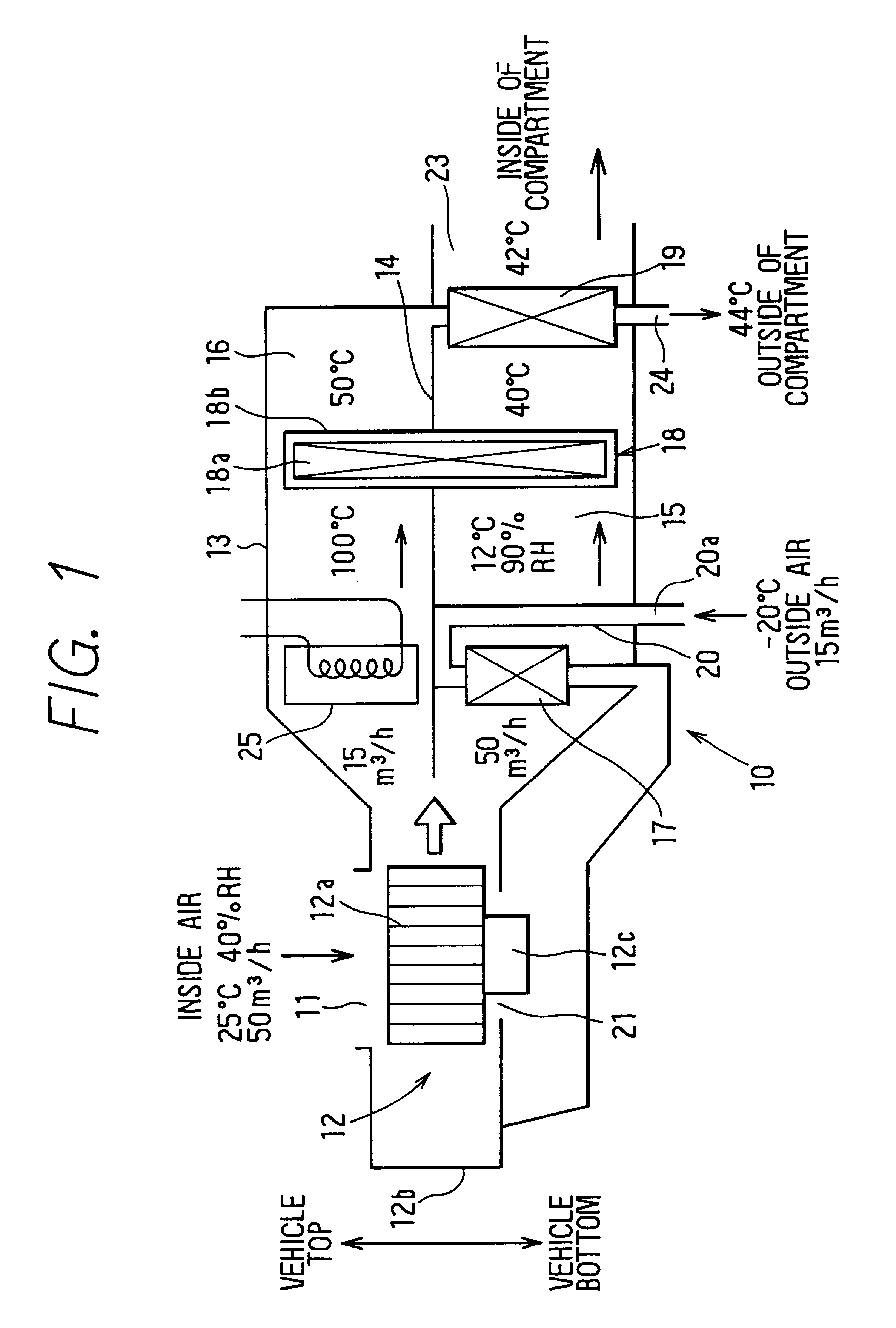
According to another aspect of the invention, the drying agent cooler cools the drying agent unit with outside air. Because the outside air temperature is often around 0.degree. C. during the winter, the low-temperature outside air can be utilized to effectively cool the drying agent, and thereby the construction of the dehumidifier can be simplified.
With this construction, in an air-conditioning system for a vehicle having an inside / outside air 2-layer flow mode, it is possible to reduce the heat load by increasing the proportion of re-circulated inside air and to prevent fogging of the windshield glass by dehumidified inside air and outside air being mixed together and blown out through the defroster outlet.

Problems solved by technology

However, in recent years, as vehicle engines have become more efficient, the resulting temperature of the engine water has decreased, causing the heating capacity of the systems to often become insufficient.
However, even in this inside / outside air 2-layer mode, when the percentage of inside air exceeds 50%, window fogging caused by increased humidity inside the passenger compartment occurs.
However, because the amount of water adsorbed per unit of drying agent is small, a large overall amount of drying agent is necessary to obtain a required dehumidifying capacity.
As a result, various problems arise, such as increased installation space required by the system as a whole due to the volume of the drying agent, increased airflow resistance presented by the drying agent, and increased energy required to regenerate the drying agent.
As a result, the temperature of the drying agent is raised by this heat of condensation, and the dehumidifying capacity of the drying agent consequently decreases.

Method used


Image

  • Motor vehicle dehumidifier with drying agent and drying agent regenerative control
  • Motor vehicle dehumidifier with drying agent and drying agent regenerative control
  • Motor vehicle dehumidifier with drying agent and drying agent regenerative control

Examples


Embodiment Construction

)

The invention is not limited to the preferred embodiments described above, and various changes are possible. For example:

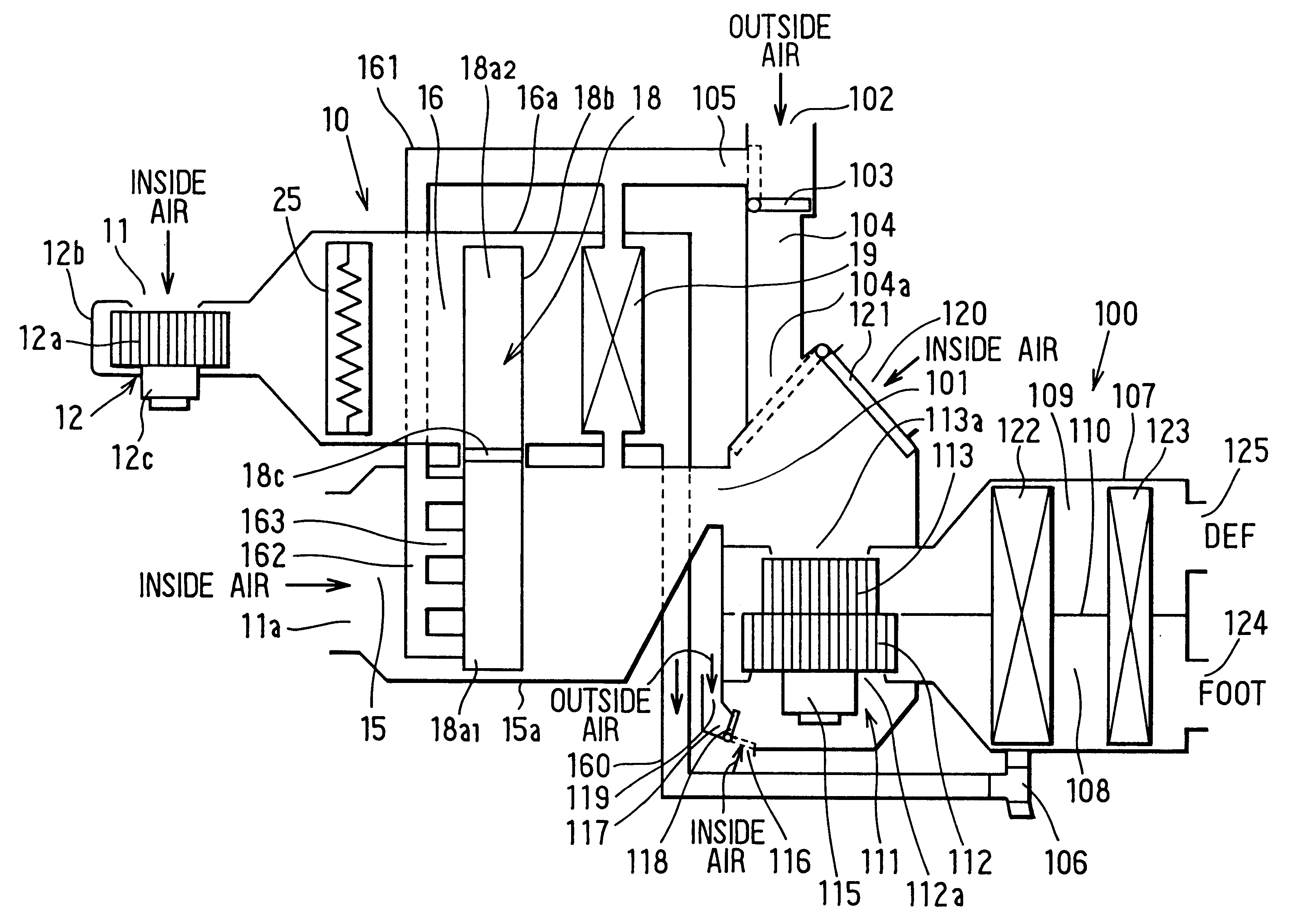
[1] Although in the first through third preferred embodiments described above the dehumidifier 10 is constructed independently of the ducting of the air-conditioning system, alternatively, as in the fourth through sixth preferred embodiments and as described in Japanese Patent Application Laid-open No. H.9-156349, the dehumidifier 10 may be integrally built in to the ducting of the air-conditioning system.

Conversely, whereas in the fourth preferred embodiment the dehumidifier 10 is built in to the ducting of the air-conditioning system, alternatively the dehumidifier 10 may be constructed independently of the ducting of the air-conditioning system in a position such as behind the passenger compartment.

[2] Although in all of the first through sixth preferred embodiments described above the drying agent unit 18 is of a rotating type for carrying out regeneration of...


PUM


Abstract

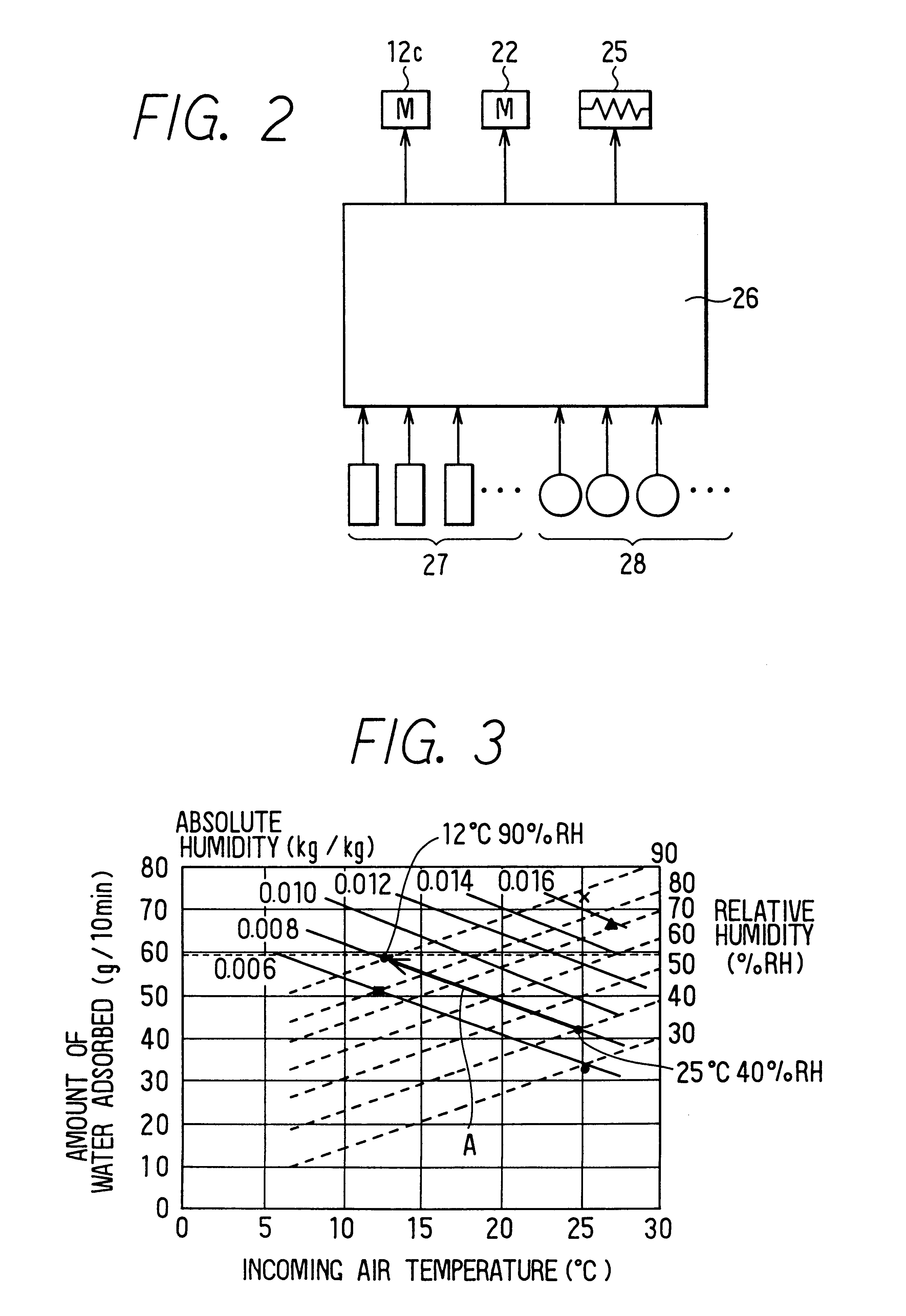
A motor vehicle dehumidifier, including a dehumidifying drying agent, that can provide a required dehumidifying capacity with a reduced overall quantity of drying agent compared to conventional drying agent-based dehumidifiers. In the present invention, a heat exchanger is disposed on an upstream side of a drying agent unit, and heat is exchanged in the heat exchanger between inside air to be dehumidified and low-temperature outside air used to cool the inside air. The air cooled by the heat exchanger flows into the drying agent unit and is dehumidified. Because the air has an increased relative humidity as a result of being cooled, the amount of water adsorbed from it per unit of drying agent is increased, as the water adsorption characteristic of the drying agent is greatly influenced by the relative humidity of the air passing over it, and is markedly improved by an increase in the relative humidity of that air.

Description

This application is related to, and claims priority in, Japanese patent application Nos. Hei. 10-4884, 10-224448, and 10-313713, each being incorporated herein by reference.1. Field of the InventionThis invention relates generally to vehicle air conditioning systems, and more particularly to a vehicle air conditioning system dehumidifier for dehumidifying ventilation air via a drying agent.2. Description of the Related ArtIn automotive vehicle air-conditioning systems, a passenger compartment is typically heated by utilizing warm water from an engine as a heat source. However, in recent years, as vehicle engines have become more efficient, the resulting temperature of the engine water has decreased, causing the heating capacity of the systems to often become insufficient.To eliminate the above heating capacity deficiency, many conventional systems increase the percentage of inside air taken in to reduce the heating load. Specifically, an auxiliary door for mixing inside air with out...

Claims


Application Information

Patent Timeline
IPC IPC(8): B60H3/06B60H3/00B60H3/02F24F3/14
CPCB60H3/024F24F3/1423B60H2003/028F24F2203/102F24F2203/1036F24F2203/106F24F2203/1068F24F2203/108F24F2203/1084B60H1/039
Inventor TAKAHASHI, KOJISHIROTA, YUICHIBAN, KOICHI
Owner DENSO CORP
Learn More