Machining center in which tool holders have a multiple coupling with a cover

a technology of multiple couplings and machining centers, which is applied in the field of machining centers, can solve the problems of reducing the reproducibility of machining operations, reducing the accuracy of machining operations, and disadvantageous handling of workpieces and workpiece holders, and reducing the time from workpiece to workpiece with the known machining center

Inactive Publication Date: 2001-03-27
CHIRON WERKE
View PDF4 Cites 7 Cited by
  • Summary
  • Abstract
  • Description
  • Claims
  • Application Information

AI Technical Summary

Problems solved by technology

It has been found that with the known machining center, the handling of the workpieces and workpiece holders is disadvantageous particularly when bulky and/or heavy workpieces are to be machined.
On the one hand, surprisingly, the machining accuracy and the reproducibility of the machining operation decrease when heavier and/or more bulky workpieces are used.
This means, however, that in order to achieve high machining accuracy and reproducibility in the machining of heavy and/or bulky workpieces, the workpiece-to-workpiece time is reduced with the known machining center, which of course is disadvantageous.
Specifically, the inventors of the present a...

Method used


Image

  • Machining center in which tool holders have a multiple coupling with a cover
  • Machining center in which tool holders have a multiple coupling with a cover
  • Machining center in which tool holders have a multiple coupling with a cover

Examples


Embodiment Construction

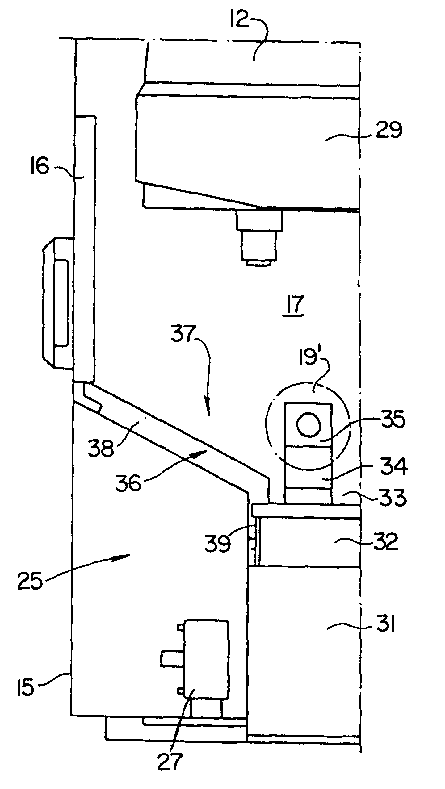
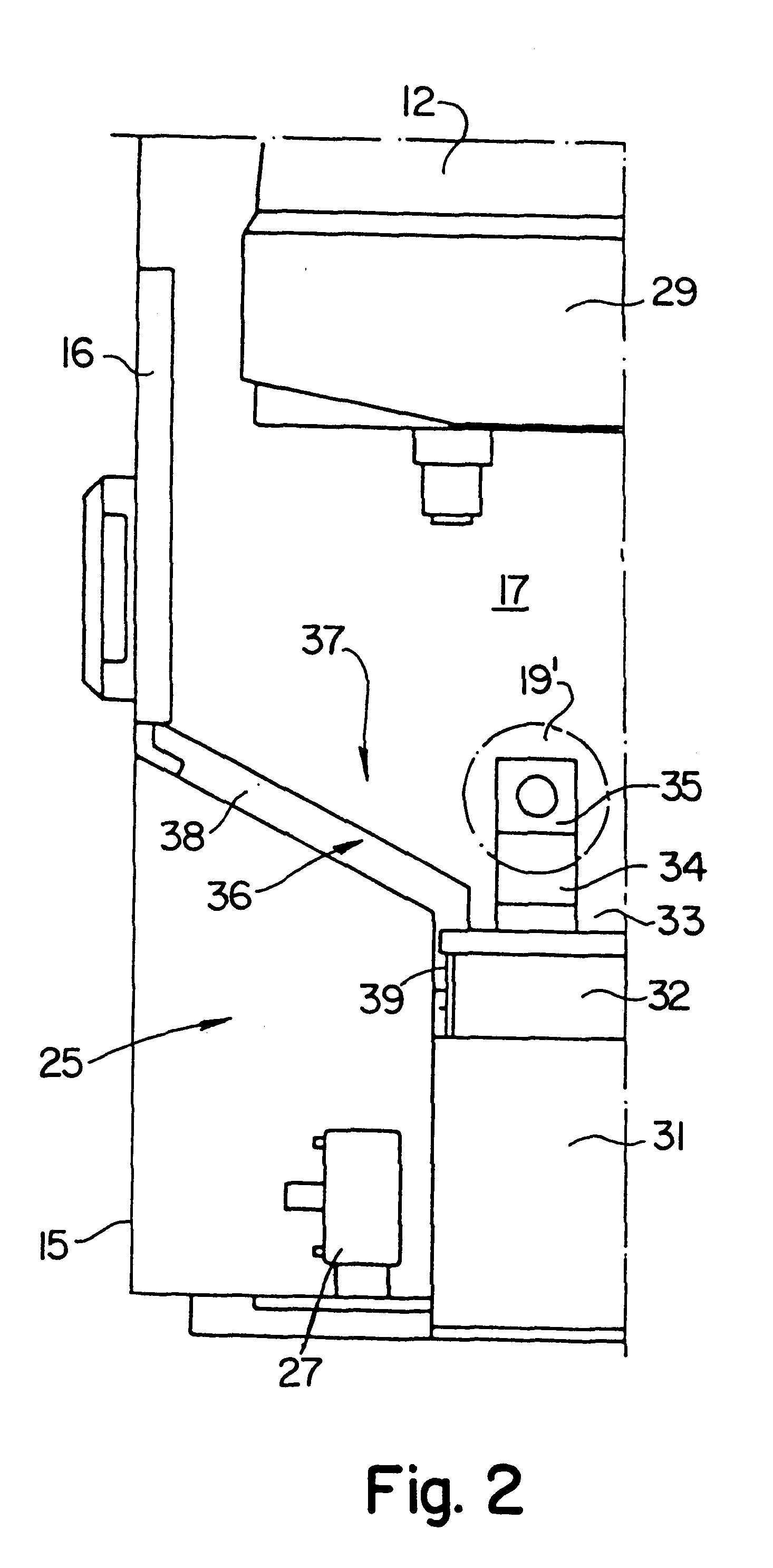
FIG. 1 shows, in a frontal view, a machining center 10 in which machine tools 11, 12, and 13 (merely indicated) are arranged next to one another. In addition to machine tools 11, 12, and 13, a loading / unloading station 14 is provided.

Machine tools 11, 12, 13 have an enclosure 15 which surrounds them completely and in which an operator door 16, through which an operator gains access to a working space 17, is provided for each machine tool 11, 12, 13. Retooling and service operations are performed for the individual machine tools 11, 12, 13 through this operator door 16.

A clamping station 18 (indicated merely schematically), in which individual workpiece holders 19 are equipped with workpieces 21 to be machined, is provided in loading / unloading station 14. Workpiece holders 19 equipped in this manner with workpieces 21 are transported by means of a loading mechanism 22 to the individual machine tools 11, 12, 13, and there inserted into the respective working space 17 and machined. Onc...


PUM

PropertyMeasurementUnit
Energyaaaaaaaaaa
Displacementaaaaaaaaaa

Abstract

A machining center has machine tools which each have a working space for machining workpieces 21, a clamping station 18 in which workpieces 21 to be machined are clamped into workpiece holders 19, and a loading device which transports the workpiece holders 19 between the clamping station 18 and the working space of at least one machine tool. A multiple coupling 70 for transferring fluidic energy, which is selectably docked in the clamping station 18, is provided on the workpiece holder 19 (FIG. 5).

Description

1. Field of the InventionThe present invention relates to a machining center having a number of machine tools which each have a working space for machining workpieces, a clamping station in which workpieces to be machined are clamped into workpiece holders, and a loading device which transports the workpiece holders between the clamping station and the working space of at least one machine tool.2. Related Prior ArtA machining center of this kind is known from DE 195 16 849 A1.In the known machining center, machine tools are arranged next to one another, a loading / unloading station in which a clamping station is located being provided next to that row of machine tools. In the clamping station, workpieces are inserted into workpiece holders which are held by a pivot arm of a loading device.After the workpiece holder has been loaded with a new workpiece, the pivot arm is pivoted in and the loading device travels to one of the machine tools, where the pivot arm pivots back out and the w...

Claims


Application Information

Patent Timeline
IPC IPC(8): B23Q41/02B23Q7/14B23Q1/00B23Q7/04B23P23/00
CPCB23Q1/0018B23Q7/1426B23Q41/02Y10T409/305544Y10T82/2514Y10T483/165Y10T409/307728Y10T29/5196Y10T483/16Y10T409/3056Y10T409/308288Y10T409/30896
Inventor SCHWEIZER, ANTON
Owner CHIRON WERKE
Why Eureka
Try Eureka