Horizontal Milling-Boring Machine With Mobile Column

a technology of horizontal milling and mobile column, which is applied in the direction of boring/drilling apparatus, planing/slotting machine, large fixed member, etc., to achieve the effect of rapid column displacemen

Active Publication Date: 2008-02-21
HPT SINERGY
View PDF13 Cites 4 Cited by
  • Summary
  • Abstract
  • Description
  • Claims
  • Application Information

AI Technical Summary

Benefits of technology

[0007]limited safety because of the presence of the pit: this drawback means that fixed or movable barriers must be used, able to protect only personnel in transit not involved in the machining, but ineffective for the operators who, because of the presence of control members in the machine, have to work within the barrier-protected areas;
[0009]EP-1 362 664 describes a machine of the type with a mobile column along a bench in a horizontal axis X. The column has two halves which from their top part, enlarges towards the base, forming a large base in which each half has primary with linear synchronous motor, with the secondary being longitudinally aligned on the bench, this bench having three linear guides which, with the tracks disposed in the base of the halves of the column, allows rapid displacement of the column along the axis X without requiring the top guide of the column.

Problems solved by technology

At the same time this known solution has also resulted in certain drawbacks, and in particular:cost: considering that a pit can have a depth of 2 metres, a width of 4 metres and a length of 15 metres, it is immediately apparent that a pit requires excavation work of more than one hundred cubic metres, a lining for the bottom and side walls of the pit which is impermeable to the refrigeration and lubrication liquids normally used during machining, walkways for operator movement in proximity to the machine and / or workpiece, a conveyor for machining swarf and chippings, located in the bottom of the pit, a tray provided in the bottom of the pit for collecting said refrigeration and lubrication liquids, and a bilge pump for transferring the liquids from the tray to the main machine tank;limited safety because of the presence of the pit: this drawback means that fixed or movable barriers must be used, able to protect only personnel in transit not involved in the machining, but ineffective for the operators who, because of the presence of control members in the machine, have to work within the barrier-protected areas;the fact that the installation area is suitable only for this exclusive use; in reality, the pit could always be filled in and the floor of the room in which the machine was installed be restored, however this would involve considerable difficulties and high costs for remaking the floor, and for repeating the operations involved in forming a new pit in a different area.

Method used


Image

  • Horizontal Milling-Boring Machine With Mobile Column
  • Horizontal Milling-Boring Machine With Mobile Column
  • Horizontal Milling-Boring Machine With Mobile Column

Examples


first embodiment

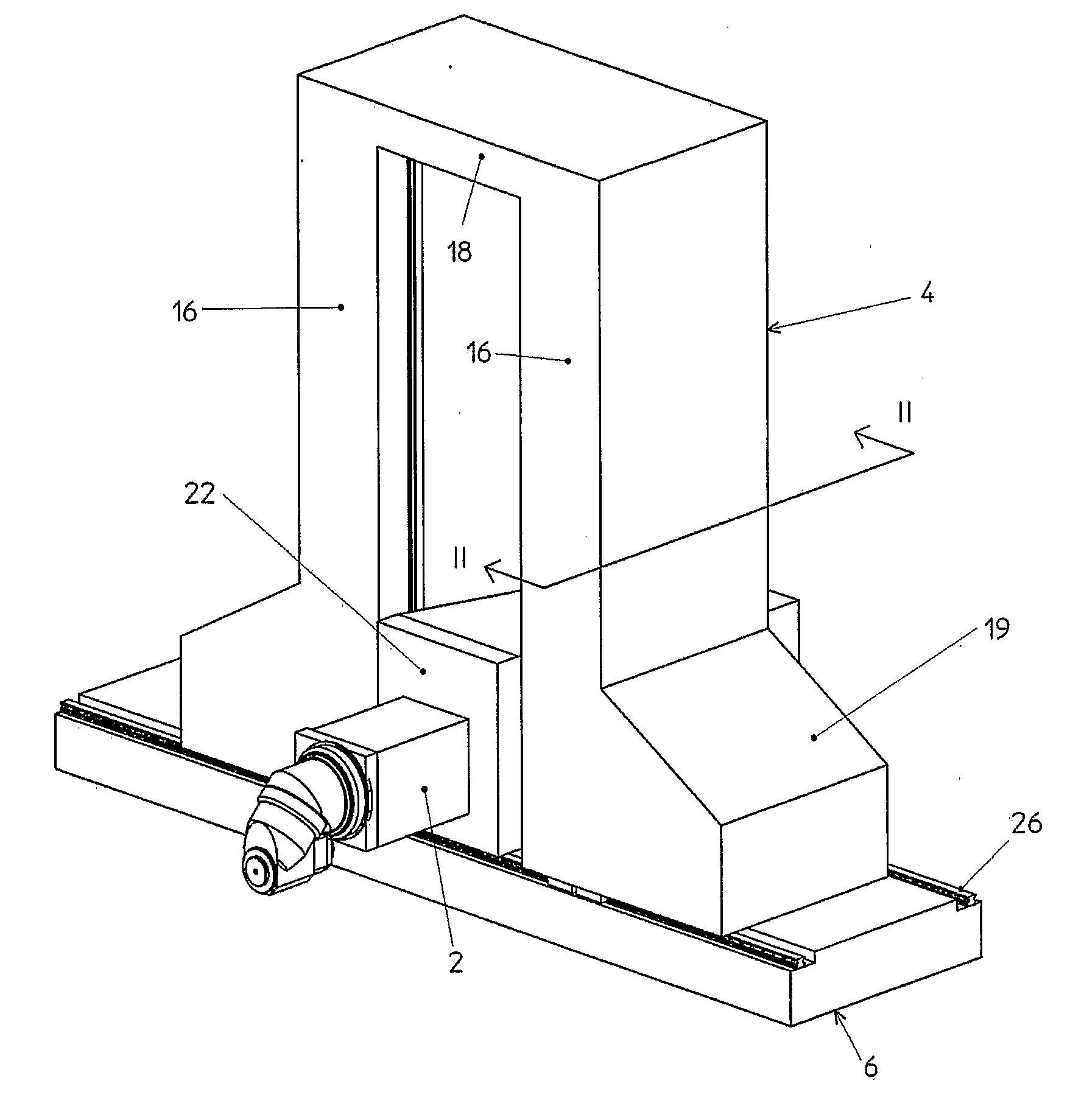
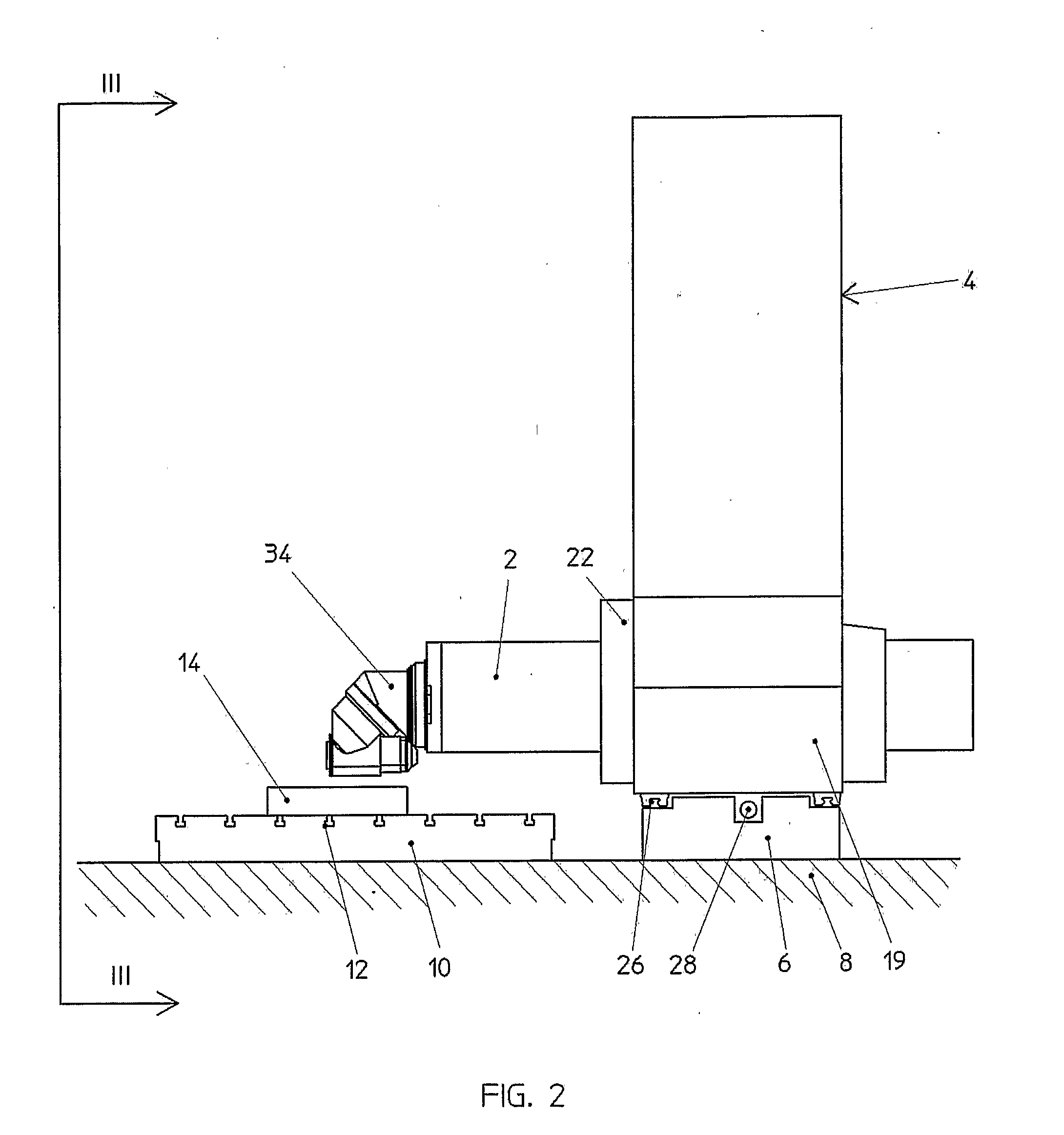
[0020]As can be seen from FIGS. 1-4, the milling-boring machine of the invention is essentially a machine of known mobile column type, i.e. with a horizontal slide 2 movable axially and also movable vertically along a column structure 4, which itself is movable horizontally in a direction perpendicular to the axis of the slide 2, along a bed 6 anchored to the floor 8.

[0021]More specifically, not only the bed 6 is anchored to the floor 8 but also a work table 10 separated from the bed and provided with grooves 12, on which the workpiece 14 to be machined can be fixed in traditional manner.

[0022]The column structure 4 is of symmetrical portal type and comprises a pair of columns 16, which are joined together upperly by a crosspiece 18 and are prolonged lowerly into a pair of portions 19, the function of which is to support the column structure 4 on the bed 6 in a stabilized manner.

[0023]A carriage 22 supporting and axially guiding the slide 2 is slidable vertically along the facing in...

second embodiment

[0034]This embodiment adds to the advantages of the preceding a greater robustness and a greater ease of construction while, as in the case of the second embodiment, enabling the guide rail 26 to be interposed between outer lateral surfaces of the bed 6 and the facing lateral surfaces of the lower crosspieces 20.


PUM

PropertyMeasurementUnit
Widthaaaaaaaaaa

Abstract

A horizontal milling-boring machine including a horizontal bed anchored to the floor, a column structure supported by the bed and slidable therealong, a slide carriage slidable vertically along said column structure, and a slide supporting the tool head and movable axially to said carriage in a direction perpendicular to the axis of said bed, characterized in that: said bed is monolithic and is separated from the work table,—said column structure is formed as a portal, with two columns connected together by an upper crosspiece and provided lowerly, for their support on the bed, with portions lying external to the opening of said portal, which is delimited laterally by said columns and extends lowerly into proximity with said bed—said slide carriage is slidable along the facing internal walls of said columns,—guide means and drive means being interposed between said column structure and said bed.

Description

BACKGROUND OF THE INVENTION[0001]The present invention relates to a horizontal milling-boring machine with mobile column.[0002]Milling machines of mobile column type are known comprising a horizontal bed anchored to the floor, a column carriage horizontally slidable along said bed, a column structure supported by said carriage, a slide carriage slidable vertically along said column structure, a slide slidable horizontally along said carriage in a direction perpendicular to the longitudinal axis of said bed, and a spindle head mounted on the end of said slide and facing a work table to which the workpiece to be machined is fixed.[0003]A recurrent problem in these milling machines consists of the fact that the bed and the column carriage result in an excessive height of the spindle axis from the work table, this being a serious impediment both to accessibility and visibility of the workpiece being machined, especially for tall regions of the workpiece.SUMMARY OF THE INVENTION[0004]To ...

Claims


Application Information

Patent Timeline
IPC IPC(8): B23Q1/01B23Q1/62
CPCB23Q1/01B23Q1/626Y10T409/307728Y10T408/91Y10T409/309576
Inventor GUELI, FRANCESCOPICCOLO, GABRIELE
Owner HPT SINERGY
Why Eureka
Try Eureka