
Electrostatic charge removing apparatus

a technology of electrostatic charge and apparatus, which is applied in the direction of machine/engine, filtration separation, separation process, etc., can solve the problems of fuel filter 4 becoming high in cost, increasing weight as a whole, and insufficient removal of electrostatic charge generated in the filter portion 4a

Inactive Publication Date: 2001-01-02
KYOSAN DENKI KABUSHIKI KAISHA +1
View PDF9 Cites 71 Cited by
  • Summary
  • Abstract
  • Description
  • Claims
  • Application Information

AI Technical Summary

Problems solved by technology

However, there are the following problems in the aforementioned electrostatic charge removing apparatus in the conventional fuel supply system shown in FIG. 8.
However, in a system to ground the conventional case 4D, the electrostatic charge generated in the filter portion 4A cannot be sufficiently removed.
Further, since a conductive material costs high and is heavy in weight, the fuel filter 4 becomes high in cost and increases in weight as a whole if the entire case 4D having a large capacity of the fuel filter 4 is formed of a conductive material.

Method used


Image

  • Electrostatic charge removing apparatus
  • Electrostatic charge removing apparatus
  • Electrostatic charge removing apparatus

Examples


first embodiment

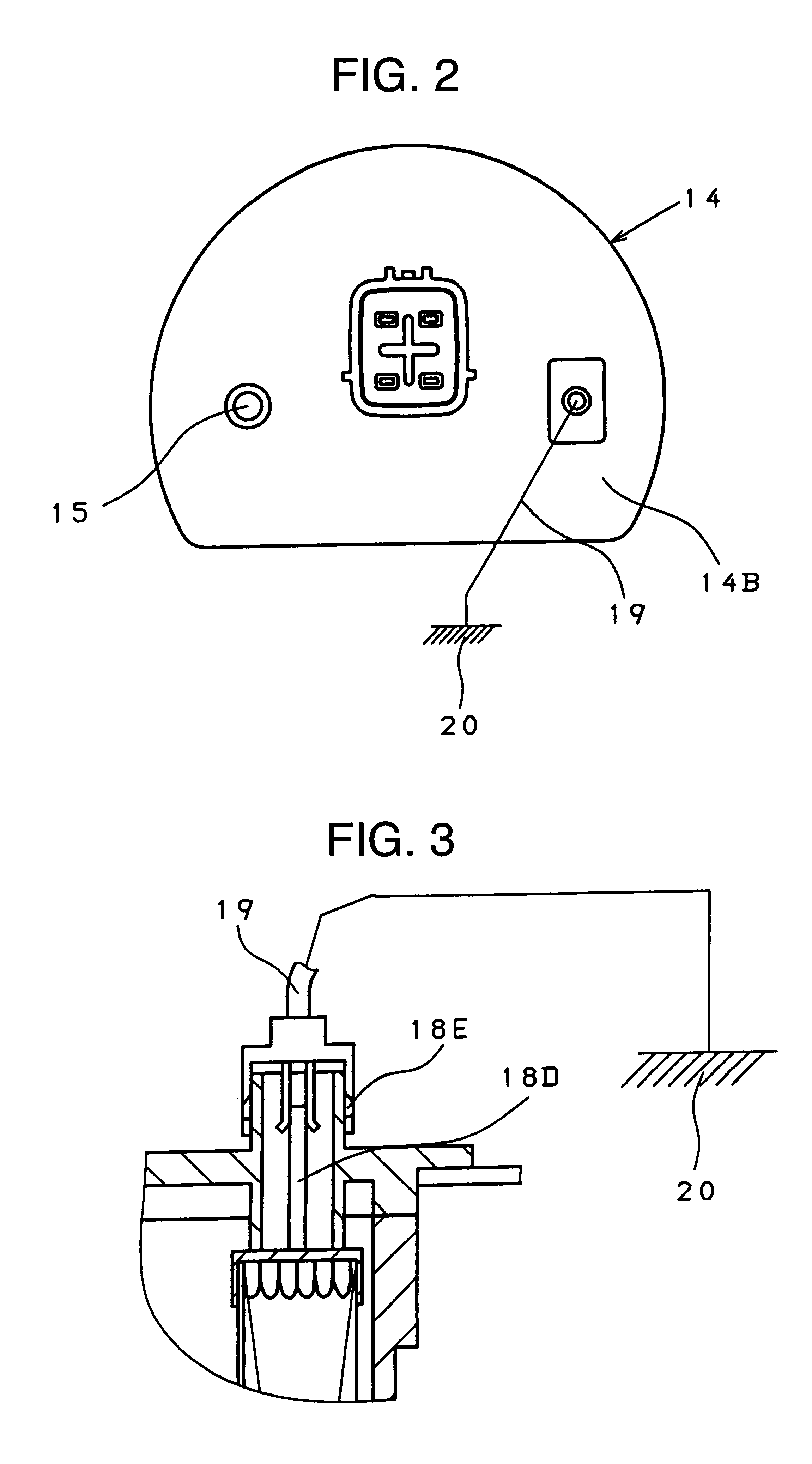
An electrostatic charge removing apparatus according to the invention will be now described with reference to FIGS. 1 to 3, wherein FIG. 1 is a schematic sectional view showing a fuel filter, FIG. 2 is a plan view of FIG. 1 and FIG. 3 is a sectional view partially enlarging one end plate of the fuel filter in FIG. 1.

In the first embodiment shown in FIGS. 1 to 3, one of end plates that hold a filter portion of the fuel filter is grounded.

That is, a fuel pump 12 is disposed inside a fuel tank 11, and a fuel filter 13 is connected to an inlet 12A provided at the upper stream of the fuel pump 12. The fuel filter 13 removes relatively large foreign matters in fuel and is formed of a net body.

A fuel filter 14 is connected to an outlet 12B provided at the downstream of the fuel pump 12. The fuel filter 14 is a normal fuel filter for removing even small foreign matters in fuel.

A filter portion 14A formed of a filter paper, etc. is provided in the fuel filter 14, and fuel discharged from the...

fourth embodiment

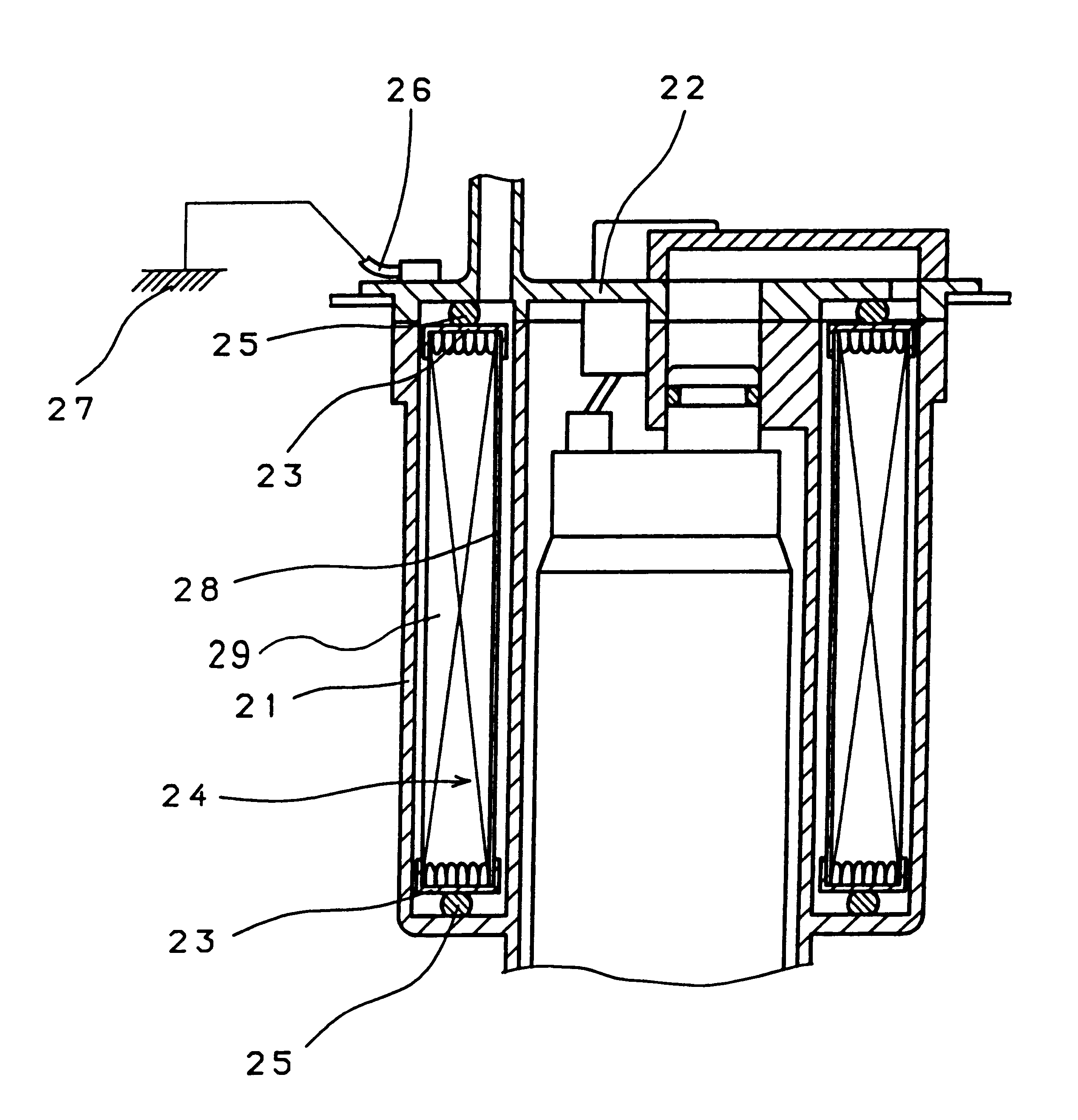
In the fourth embodiment shown in FIG. 6, electrostatic charge generated in the filter portion 24 is escaped to the ground 27 via the end plates 23, the seal members 25 and the lead 26.

In the fifth embodiment shown in FIG. 7, a case 31 is covered with a cap 32. The case 31 is formed of a nonconductive material and the cap 32 is formed of a conductive material. End plates 33 are formed of a conductive material or a nonconductive material, while a filter portion 34 is clamped and held by the cap 32 and the end plates 33. The filter portion 34 is formed of a conductive material or nonconductive material, and it divides the inner portion of the case 31 into an inner side and an outer side. The filter portion 34 is connected to the cap 32 and it seals an inlet chamber and an outlet chamber respectively formed in the inner and outer sides of the case 31 partitioned by the filter portion 34. A lead 36 for grounding is connected to the cap 32, and it is also connected to the ground 37. Seal...


PUM

PropertyMeasurementUnit
Weightaaaaaaaaaa
Electrical conductivityaaaaaaaaaa
Electrical conductoraaaaaaaaaa

Abstract

An electrostatic charge removing apparatus in a fuel filter is capable of reliably removing electrostatic charge generated in a fuel filter and of reducing cost and weight of the fuel filter by escaping or discharging the electrostatic charge from parts of the fuel filter other than a case of the fuel filter. The fuel filter includes a filter portion that is connected to an outlet of a fuel pump disposed in a fuel tank and is clamped by end plates, a case housing the filter portion therein, wherein the end plates are formed of a conductive material, and a projection that penetrates a cap is formed on one end plate and is grounded.

Description

1. Field of the InventionThe invention relates to an electrostatic charge removing apparatus in a fuel filter installed in a fuel supply system of an automobile, more particularly to an electrostatic charge removing apparatus in a fuel filter installed in a fuel supply system wherein a fuel supply pump and a fuel filter are provided in a fuel tank.2. Related ArtIt has been hitherto known to provide a fuel supply pump and a fuel filter in a fuel tank so as to simplify a fuel supply system and at the same time to reduce the influence of heat on the fuel filter.In the known fuel supply system, a case of a fuel filter is formed of a conductive body and it is grounded to discharge electrostatic charge so as to remove the electrostatic charge that is charged in the fuel filter.This is described with reference to FIG. 8 wherein a fuel pump 2 is disposed inside a fuel tank 1, and a fuel filter 4 is connected to an outlet 3 of the fuel pump 2. The fuel filter 4 is a normal fuel filter for re...

Claims


Application Information

Patent Timeline
IPC IPC(8): B01D29/05B01D29/01B01D35/027B01D35/00F02M37/22B01D35/02F02M37/44F02M37/50
CPCB01D29/055B01D35/027B01D35/0273F02M37/22B01D29/15B01D29/54B01D29/56B01D35/26B01D2201/50F02M2037/228F02M37/50F02M37/44
Inventor SEKINE, HITOSHISAWADA, KAZUTOYAMADA, KATSUHISA
Owner KYOSAN DENKI KABUSHIKI KAISHA
Learn More