Fish ladder and its construction
a ladder and ladder technology, applied in the field of fishways, can solve the problems of high cost of fish passages, long distance to be covered, complex, etc., and achieve the effect of reducing the number of basins and being less expensiv
- Summary
- Abstract
- Description
- Claims
- Application Information
AI Technical Summary
Benefits of technology
Problems solved by technology
Method used
Image

Examples
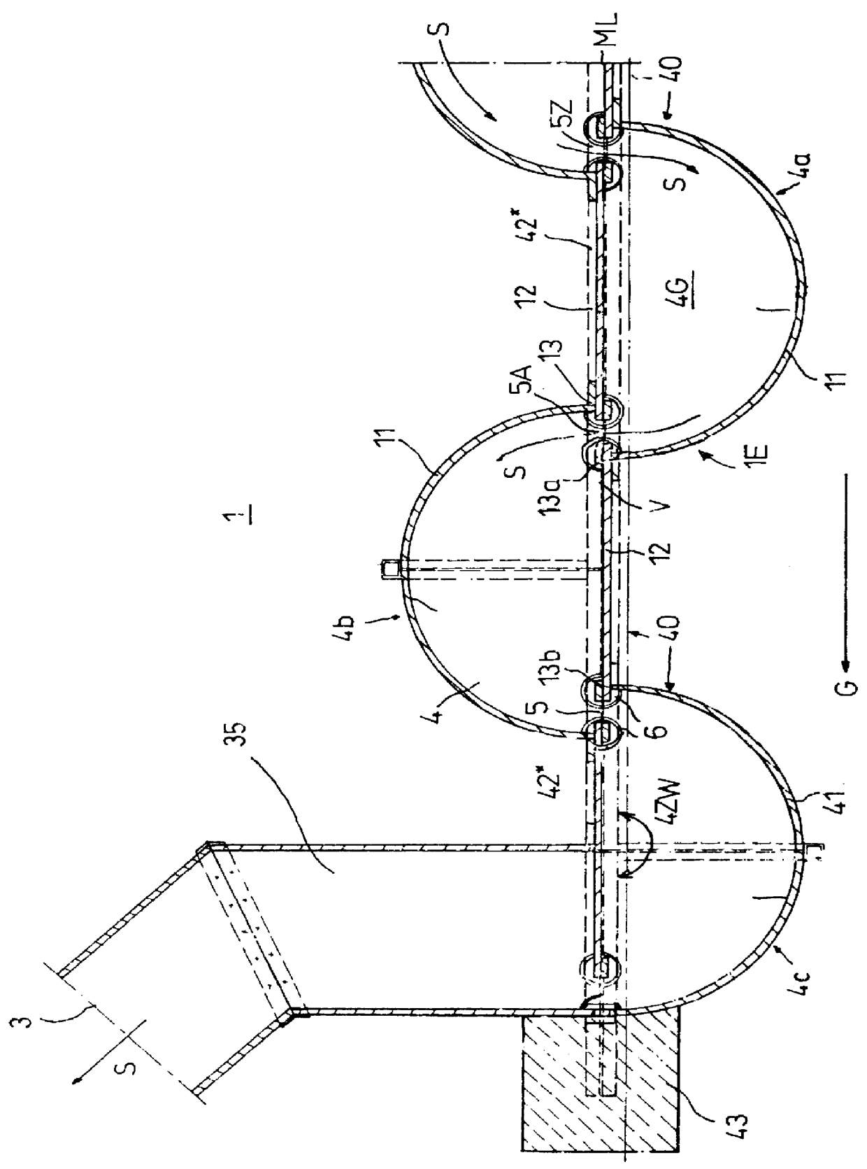
first embodiment
This first embodiment is connected to the flowing watercourse (31F) via a downstream connection trench (35) and an upstream connection trench (32) (not shown in the drawing). The connection trenches (32, 35) are fiber-cement channels with rectangular cross sections that are open along the top, each of which connects the respective uppermost and lowermost semi-cylindrical basin (4) to the flowing watercourse (31F). A multi-part construction permits an optimal flexible connection to the flowing watercourse (31F) and the construction principle also permits the construction of angular fishways (1).
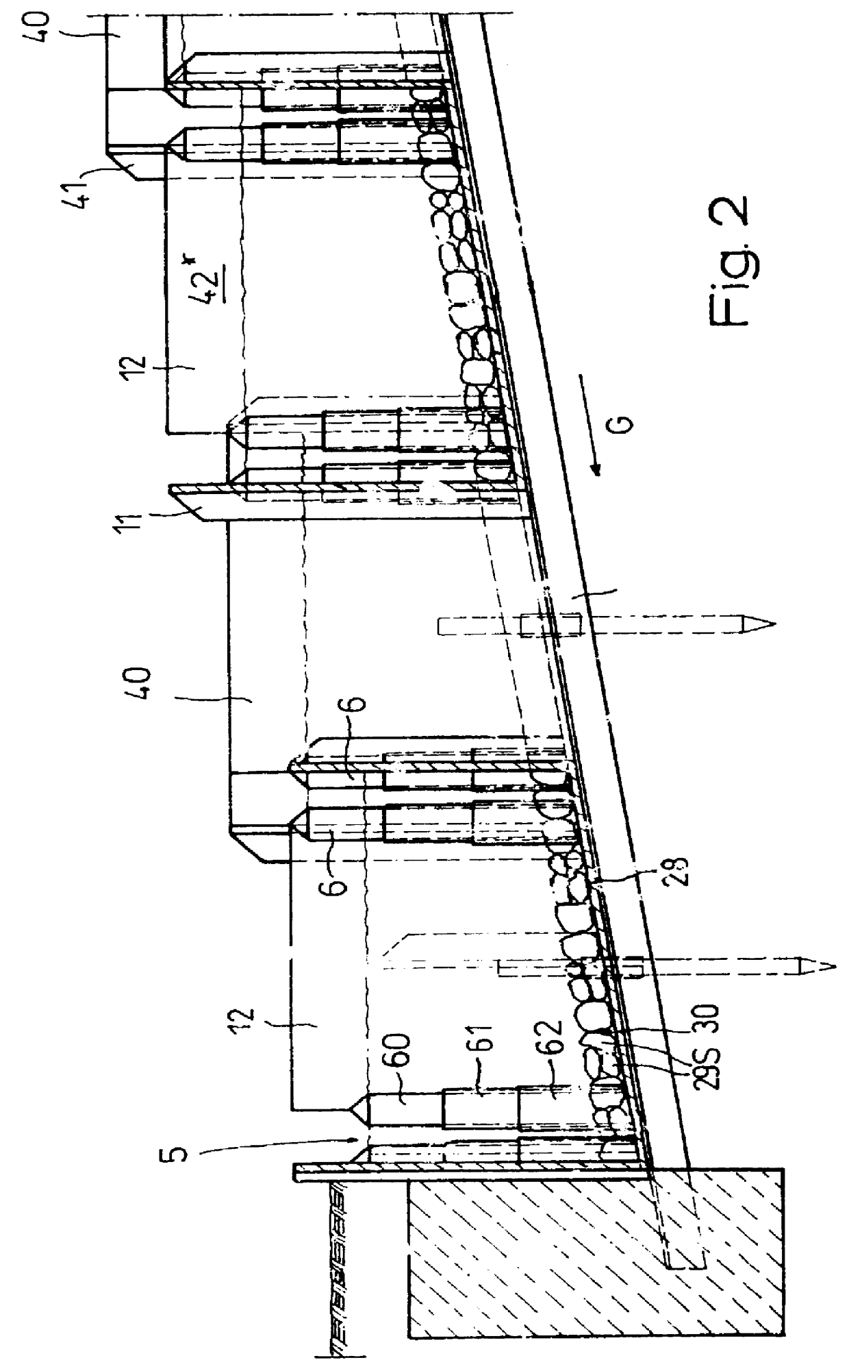
FIG. 2 shows a through-flow slot (5) whose cross section changes along its height. The constriction of the cross section reduces the amount of water required for a safe operation of the system (1) and permits a precise adjustment of the water level. To change the cross section, two shorter partially cylindrical pipes (61, 62) with an opening on their longitudinal sides are slipped on, as sleev...
second embodiment
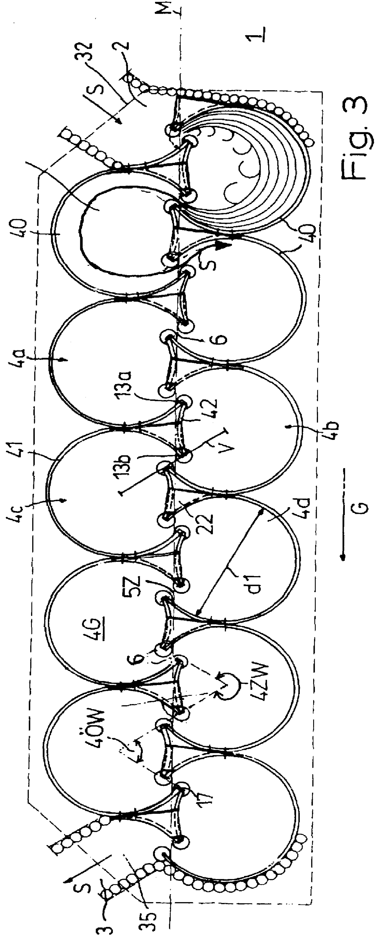
FIGS. 3 and 4 show a fishway (1). The basins (4) consist of two pipe sections (41*, 42) of different sizes as a first and second basin wall (11, 12), which are arranged opposite one another to form the segment of a circle as the base area (4G). The first basin wall (11) has a center angle of 300.degree. and the second basin wall (12) has a center angle of 50.degree.. The second basin wall (12) is arranged approximately on the chord of the first basin wall (11).
The illustrated system (1) consists of eleven steps, with the first basin walls (11) oriented with their alternating openings (40) towards the center line (M) of the fishway (1). The center points (MP) of the basins (4a, 4c; 4b, 4d) that have the same orientation are located on two parallel, imaginary straight lines (G1, G2) extending in the direction of the slope (G). The center points (MP) of the successive basins (4a, 4b, 4c, 4d) are located on an imaginary zigzag-shaped connecting line (V) with the resulting angles between...
third embodiment
FIGS. 13 through 15 show a further embodiment of a fishway (1) integrated into a catchment reservoir (31T) in the form of a structure resting against an existing structure. This third embodiment of the fishway (1) is characterized by a very compact design.
For space reasons, at least the upstream portion (1O) of the system consists of basins (4) with three inner partial basins (4T) as shown in FIG. 10, since only a short distance is available for the upstream portion (1O) of the system. The slope (G) is approximately 30% here, with a height of fall of 25 cm. The upstream portion (1O) of the system is supported on the floor side by angular supporting walls projecting into the fluctuation area behind the masonry dam (34M).
The basins (4) according to FIG. 10 consist of two basin walls (11, 12), arranged in an opposite direction, made of pipe sections (41*, 42), with a first basin wall (11) having a center angle (4ZW) of approximately 340.degree. and a second basin wall (12) having a cen...
PUM
 Abstract
Description
Claims
Application Information
 - R&D
- Intellectual Property
- Life Sciences
- Materials
- Tech Scout
- Unparalleled Data Quality
- Higher Quality Content
- 60% Fewer Hallucinations
Browse by: Latest US Patents, China's latest patents, Technical Efficacy Thesaurus, Application Domain, Technology Topic, Popular Technical Reports.
© 2025 PatSnap. All rights reserved.Legal|Privacy policy|Modern Slavery Act Transparency Statement|Sitemap|About US| Contact US: help@patsnap.com