Fluid storage and dispensing system

a technology of gas dispensing system and liquid storage, which is applied in the direction of container discharging from pressure vessels, non-pressured vessels, chemical vapor deposition coatings, etc., can solve the problems of significant lag time in the dispensing operation, difficult discharging of interiorly disposed heating coils or other heating elements in the zeolite bed itself, and difficult discharging of liquid storage. achieve the effect of improving efficiency, cost and ease of us

Inactive Publication Date: 2000-07-18
ENTEGRIS INC
View PDF40 Cites 286 Cited by
  • Summary
  • Abstract
  • Description
  • Claims
  • Application Information

AI Technical Summary

Benefits of technology

to provide an improved fluid storage and dispensing system for the selective dispensing

Problems solved by technology

The method disclosed in the Knollmueller patent is disadvantageous in that it requires the provision of heating means for the zeolite material, to heat the zeolite to sufficient temperature to desorb the previously sorbed arsine from the zeolite in the desired quantity.
The use of a heating jacket or other means exterior to the vessel holding the arsine-bearing zeolite is problematic in that the vessel typically has a significant heat capacity, and therefore introduces a significant lag time to the dispensing operation.
Further, heating of arsine causes it to decompose, resulting in the formation of hydrogen gas, which introduces an explosive hazard into the process system.
Additionally, such thermally-mediated decomposition of arsine effects substantial increase in gas pressure in the process system, which may be extremely disadvantageous from the standpoint of system life and operating efficiency, as well as safety concerns.
The provision of interiorly disposed heating coil or other heating elements in the zeolite bed itself is problematic since it is difficult with such means to uniformly heat the zeolite bed to achieve the desired uniformity of arsine gas release.
The use of heated carrier gas str

Method used


Image

  • Fluid storage and dispensing system
  • Fluid storage and dispensing system
  • Fluid storage and dispensing system

Examples


Embodiment Construction

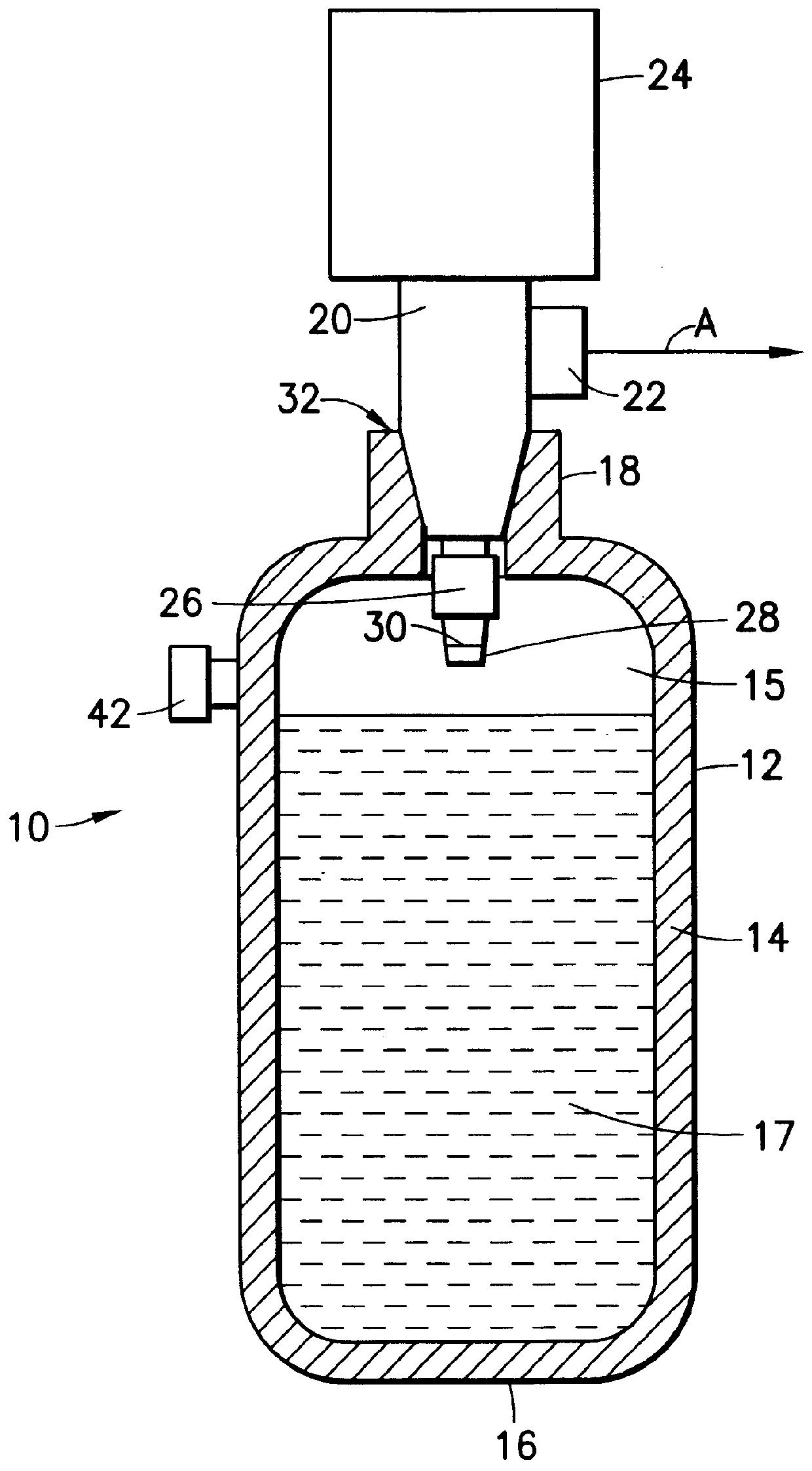
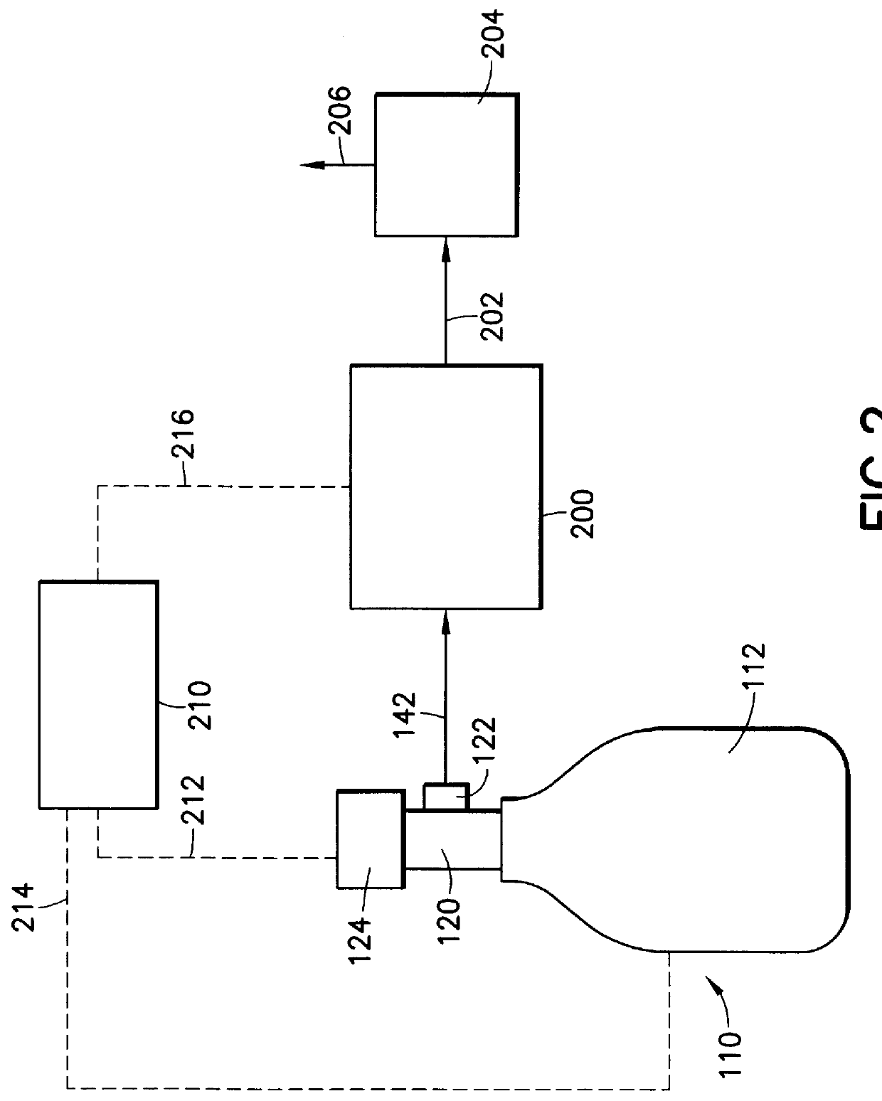
The present invention is based on the discovery that a fluid storage and dispensing system, of a type presenting an alternative to the fluid storage and dispensing system of Tom et al. U.S. Pat. No. 5,518,528, may be easily fabricated by disposing a fluid pressure regulator between a confined liquid volume and a gas dispensing assembly including a gas flow control element such as a gas flow shut off valve, mass flow controller, or the like.

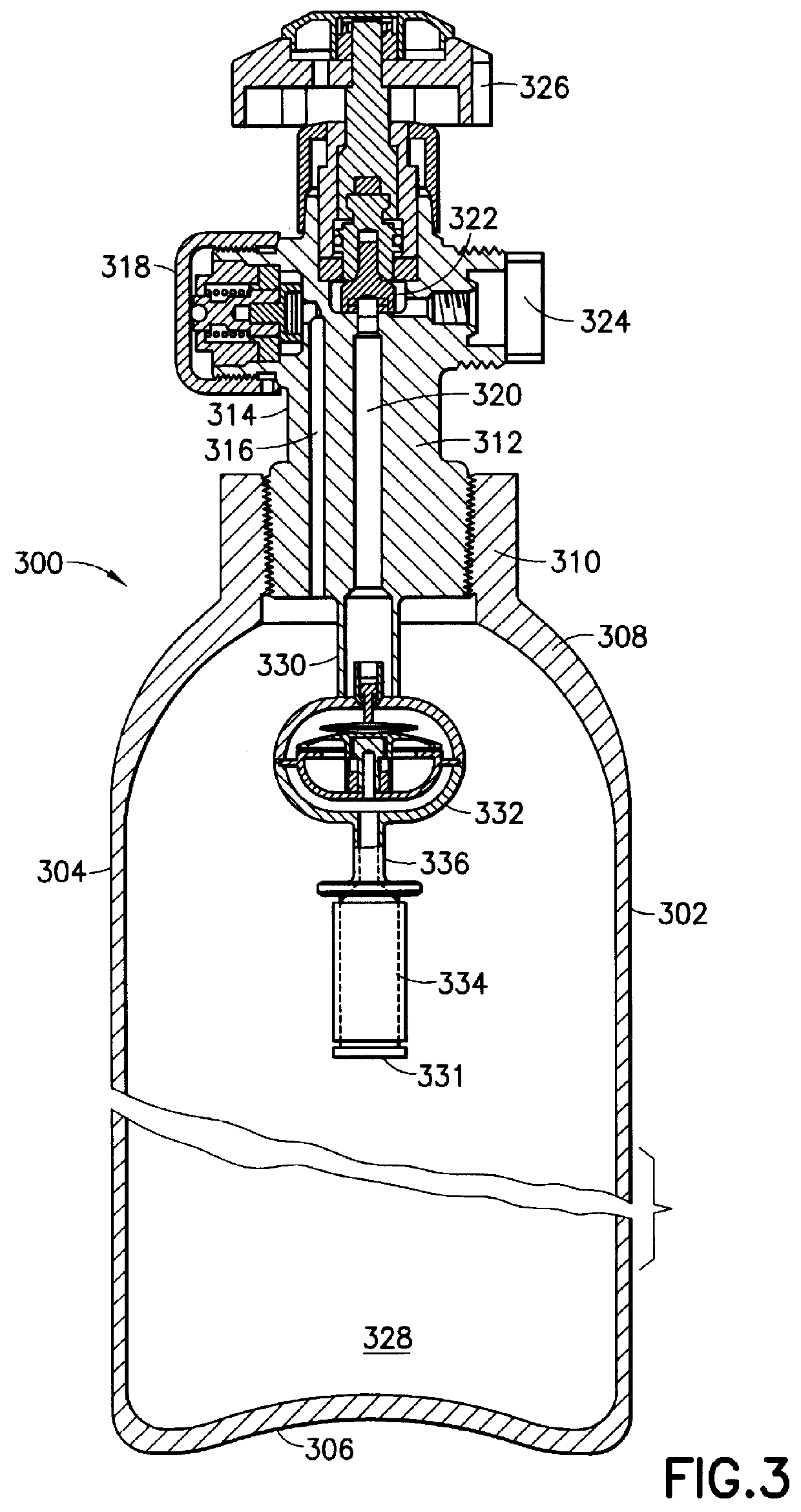
Ancillary to this discovery is the finding that the fluid pressure regulator may be advantageously interiorly disposed in the fluid storage and dispensing vessel, so that it is protected by the vessel, e.g., cylinder casing or housing, from impact, environmental exposure and damage.

Although the fluid pressure regulator is preferably interiorly disposed in the fluid storage and dispensing vessel, it is possible to dispose such element exteriorly of the vessel in the broad practice of the invention. The invention therefore broadly contemplates the p...


PUM

PropertyMeasurementUnit
Lengthaaaaaaaaaa
Lengthaaaaaaaaaa
Lengthaaaaaaaaaa

Abstract

A fluid storage and dispensing system comprising a vessel for holding a fluid at a desired pressure. The vessel has a pressure regulator, e.g., a single-stage or multi-stage regulator, associated with a port of the vessel, and set at a predetermined pressure. A dispensing assembly, e.g., including a flow control means such as a valve, is arranged in gas/vapor flow communication with the regulator, whereby the opening of the valve effects dispensing of gas/vapor from the vessel. The fluid in the vessel may be constituted by a liquid that is confined in the vessel at a pressure in excess of its liquefaction pressure at prevailing temperature conditions, e.g., ambient (room) temperature. In another aspect, the vessel contains a solid-phase sorbent material having sorbable gas adsorbed thereon, at a pressure in excess of 50 psig. The vessel may have a >1 inch NGT threaded neck opening, to accommodate the installation of an interior regulator.

Description

1. Field of the InventionThis invention relates to a fluid storage and gas dispensing system which may be utilized to store high pressure liquid or other fluid, for dispensing of gas from the system and use of the dispensed gas in an application such as the manufacture of semiconductor devices and materials.2. Description of the Related ArtIn a wide variety of industrial processes and applications, there is a need for a reliable source of process fluid(s).Such process and application areas include semiconductor manufacturing, ion implantation, manufacture of flat panel displays, medical intervention and therapy, water treatment, emergency breathing equipment, welding operations, space-based delivery of liquids and gases, etc.U.S. Pat. No. 4,744,221 issued May 17, 1988 to Karl O. Knollmueller discloses a method of storing and subsequently delivering arsine, by contacting arsine at a temperature of from about -30.degree. C. to about +30.degree. C. with a zeolite of pore size in the ra...

Claims


Application Information

Patent Timeline
IPC IPC(8): F17C13/00F17C11/00F17C13/04F17C1/00F17C13/02F17C7/00C23C14/24C23C16/448F17C7/02F17C7/04F17C9/02H01L21/205H01L21/265H01L21/306
CPCF17C1/00F17C7/00F17C7/02F17C11/00F17C11/005F17C13/02F17C13/025F17C13/04B01J20/20B01D53/0407B01D53/0415B01D53/053F17C13/045F17D1/04F17C2205/0338F17C2205/0391F17C2270/0518Y02E60/321B01D2253/10B01D2253/102B01D2253/104B01D2253/106B01D2253/1085B01D2253/202B01D2258/0216B01D2259/40003B01D2259/4009B01D2259/40094B01D2259/40098B01D2259/4525B01D2259/455F17C2201/0109F17C2201/0114F17C2201/058F17C2205/0329F17C2205/0341F17C2205/035F17C2205/0385F17C2223/0123F17C2223/033F17C2223/035F17C2250/043Y02E60/32F17C7/04
Inventor WANG, LUPINGTOM, GLENN M.
Owner ENTEGRIS INC
Why Eureka
Try Eureka