Annealing system and annealing method integrated with laser and microwave

a laser and microwave technology, applied in the field of annealing system and annealing method, can solve the problems of large-sized wafer annealing, microwave resonant cavity heating rate is limited to 200° c./min, and is suitable for mass-processing

Pending Publication Date: 2022-11-17
HIGHLIGHT TECH +1
View PDF0 Cites 0 Cited by
  • Summary
  • Abstract
  • Description
  • Claims
  • Application Information

AI Technical Summary

Benefits of technology

The annealing system and method in this patent use laser and microwave energy to heat up the object being annealed, which has several advantages. First, it can increase the object's ability to absorb laser energy, reducing the amount of laser energy needed for the annealing process. Second, it can help to prevent damage to the object from sudden changes in temperature. Third, it can help to avoid defects caused by large temperature differences and excessive diffusion of implanted ions. Overall, this system and method can improve the efficiency and quality of the annealing process.

Problems solved by technology

Although microwave annealing can provide faster heating and cooling rates, the heating rate of microwave resonant cavity is limited to 200° C. / min, which is not suitable for annealing large-sized wafers, even less suitable for mass-processing.
Although laser annealing is currently used in the technology, the laser annealing energy is too concentrated on the laser spot, which is prone to the problem of excessive diffusion of implanted ions, and being limited by the area of the laser spot, the to-be-annealed object cannot be heated uniformly, resulting in an excessive temperature difference between the focal point and the non-focal point, and stress and cracks or defects can be generated easily.

Method used


Image

  • Annealing system and annealing method integrated with laser and microwave
  • Annealing system and annealing method integrated with laser and microwave
  • Annealing system and annealing method integrated with laser and microwave

Examples


Embodiment Construction

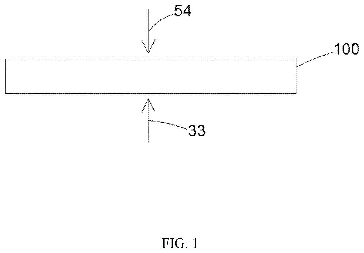
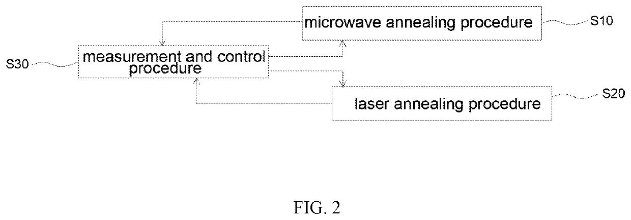
[0047]In order to understand the technical features, content and advantages of the invention and its achievable efficacies, the invention is described below in detail in conjunction with the figures, and in the form of embodiments, the figures used herein are only for a purpose of schematically supplementing the specification, and may not be true proportions and precise configurations after implementation of the invention; and therefore, relationship between the proportions and configurations of the attached figures should not be interpreted to limit the scope of the claims of the invention in actual implementation. In addition, in order to facilitate understanding, the same elements in the following embodiments are indicated by the same referenced numbers. And the size and proportions of the components shown in the drawings are for the purpose of explaining the components and their structures only and are not intending to be limiting.

[0048]Unless otherwise noted, all terms used in ...


PUM

PropertyMeasurementUnit
included angleaaaaaaaaaa
angleaaaaaaaaaa
frequency rangeaaaaaaaaaa

Abstract

Disclosed is an annealing system integrated with laser and microwave. The annealing system is provided with a microwave system, a laser system, and a measurement and control system. The microwave system provides a microwave energy to a first area of a to-be-annealed object for annealing the first area of the to-be-annealed object. The laser system uses a laser to provide a laser energy to a second area of the to-be-annealed object for annealing the second area of the to-be-annealed object. The measurement and control system monitors and controls a power of a microwave and / or a laser. The annealing system is capable of reducing a time required for an overall annealing, and also capable of avoiding cracks or defects caused by large stress differences.

Description

CROSS-REFERENCE TO RELATED APPLICATION[0001]This application claims priority to U.S. Provisional Patent Application No. 63 / 188,478, filed on May 14, 2021; claims priority from U.S. Provisional Patent Application No. 63 / 302,974, filed on Jan. 25, 2022; and claims priority from Taiwan Patent Application No. 111117039, filed on May 5, 2022, each of which is hereby incorporated herein by reference in its entireties.BACKGROUND OF THE INVENTION1. Field of Invention[0002]The invention relates to an annealing system and an annealing method, and more particularly to an annealing system and an annealing method integrated with laser and microwave.2. Related Art[0003]Although microwave annealing can provide faster heating and cooling rates, the heating rate of microwave resonant cavity is limited to 200° C. / min, which is not suitable for annealing large-sized wafers, even less suitable for mass-processing. Although laser annealing is currently used in the technology, the laser annealing energy ...

Claims


Application Information

Patent Timeline
Patent Type & Authority Applications(United States)
IPC IPC(8): H05B6/06H05B6/10B23K26/20
CPCH05B6/06H05B6/101B23K26/20H01L21/67115H01L21/67248H01L21/67253H01L21/268H01L21/324H01L22/12H01L22/20C30B33/02H05B6/80B23K26/702B23K26/705B23K26/351B23K26/0626B23K26/034B23K2101/40Y02P10/25
Inventor KOU, CHWUNG-SHANYEH, WEN-YUNG
Owner HIGHLIGHT TECH
Why Eureka
Try Eureka