Forming apparatus and article manufacturing method

a technology of forming apparatus and manufacturing method, which is applied in the field of forming apparatus and article manufacturing method to achieve the effect of both throughput and maintainability of molds

Pending Publication Date: 2022-11-10
CANON KK
View PDF2 Cites 0 Cited by
  • Summary
  • Abstract
  • Description
  • Claims
  • Application Information

AI Technical Summary

Benefits of technology

[0006]The present invention provides a technique advantageous in achieving both the throughput and the maintainability of a mold.

Problems solved by technology

As is described in Japanese Patent No. 5824380, a mold has a manufacturing error and a dimensional error.
Therefore, due to individual differences in the thickness and expanding amount of the mold, an error occurs in the distance between the mold and the substrate.
Then, when driving the mold at a high speed until the mold comes into contact with the imprint material as described in Japanese Patent No. 5745129, the mold can collide with the substrate at the high speed and be damaged.
To the contrary, the contact between the pattern surface of the mold and the imprint material can be insufficient, resulting in slow filling and a decrease in throughput.

Method used


Image

  • Forming apparatus and article manufacturing method
  • Forming apparatus and article manufacturing method
  • Forming apparatus and article manufacturing method

Examples


first embodiment

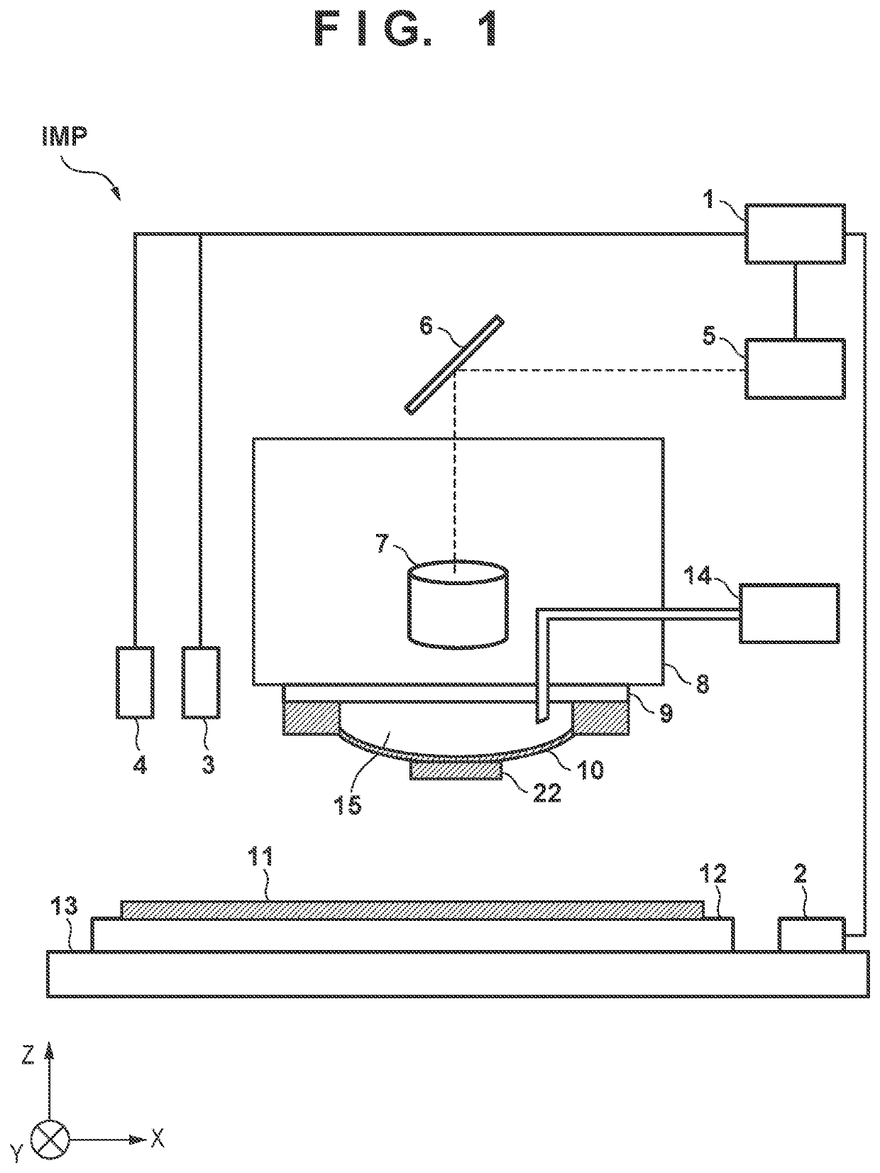
[0021]The present invention is related to a forming apparatus that performs a forming process of forming a formable material made of a curable composition on a substrate. The forming process can include a supply step of discretely supplying droplets onto a substrate, and a contact step of bringing a formable material supplied onto the substrate into contact with a mold (original or template). The forming process can further include a curing step of curing the formable material in a state in which the formable material is in contact with the mold, and a separation step of separating the cured formable material from the mold.

[0022]In this embodiment, an imprint apparatus as an example of the forming apparatus will be described. FIG. 1 is a view showing the arrangement of an imprint apparatus IMP according to the embodiment. In the specification and the drawings, directions will be indicated by an XYZ coordinate system in which the horizontal surface is set as the X-Y plane. In general...

second embodiment

[0057]In the first embodiment described above, an imprint apparatus, which transfers a pattern of a mold to an imprint material by bringing the imprint material and the mold into contact with each other, has been described as one aspect of the forming apparatus. However, the present invention is also applicable to a planarization apparatus as another aspect of the forming apparatus, which brings a formable material (composition) on a substrate into contact with a member (mold) including a planarized surface to form a planarizing film made of the composition on the substrate.

[0058]The underlying pattern on the substrate has a concave / convex profile derived from a pattern formed in the previous step. More particularly, a process substrate may have a step of about 100 nm along with a multilayer structure of a recent memory element. The step derived from the moderate undulation of the entire surface of the substrate can be corrected by the focus tracking function of a scan exposure appa...


PUM

PropertyMeasurementUnit
degrees of freedomaaaaaaaaaa
wavelength rangeaaaaaaaaaa
relative speedaaaaaaaaaa

Abstract

A forming apparatus forms a formable material using a mold including a contact region to be brought into contact with the formable material on a substrate. The apparatus includes a controller configured to perform processing of bringing the contact region and the formable material on the substrate into contact with each other. The controller controls the processing so as to bring the mold and the substrate close to each other at a first relative speed and then bring the mold and the substrate close to each other at a second relative speed lower than the first relative speed, and controls switching from the first relative speed to the second relative speed so as to compensate a manufacturing error of the mold.

Description

BACKGROUND OF THE INVENTIONField of the Invention[0001]The present invention relates to a forming apparatus and an article manufacturing method.Description of the Related Art[0002]An imprint apparatus has been put into practice as one of mass production lithography apparatuses for semiconductor devices and the like. The imprint apparatus cures an imprint material supplied onto a substrate in a state in which the imprint material is in contact with a mold and separates the mold from the cured imprint material, thereby forming a pattern of the imprint material on the substrate. Currently, the imprint apparatus is required to further improve the throughput.[0003]Japanese Patent No. 5745129 discloses driving control of a mold for improving the throughput. In Japanese Patent No. 5745129, before a mold comes into contact with an imprint material, the mold is driven at a high speed, and when the imprint material is filled into the pattern surface of the mold thereafter, the mold is driven ...

Claims


Application Information

Patent Timeline
Patent Type & Authority Applications(United States)
IPC IPC(8): B29C59/02B29C59/00
CPCB29C59/026B29C59/002B29C2037/90G03F7/0002H01L21/67092G03F9/7042H01L21/31144H01L21/32139
Inventor SATO, TAKAHIRO
Owner CANON KK
Why Eureka
Try Eureka