
Imaging optical system and imaging apparatus

Pending Publication Date: 2022-11-03
SONY CORP
View PDF0 Cites 0 Cited by
  • Summary
  • Abstract
  • Description
  • Claims
  • Application Information

AI Technical Summary

Benefits of technology

The patent text describes an imaging optical system and an imaging apparatus that can extend the depth of field while maintaining resolution performance. This is achieved by using an optical phase modulator with specific properties and conditions. The technical effect of this system is improved image quality and reduced blurring in the captured images. Imaging apparatuses that includes this system are also described.

Problems solved by technology

Although medical imaging equipment, for example, is demanded to be increased in resolution, the increase in resolution can cause a decrease in a depth of field.

Method used


Image

  • Imaging optical system and imaging apparatus
  • Imaging optical system and imaging apparatus
  • Imaging optical system and imaging apparatus

Examples


application examples

2. Application Examples

[0080]Described next are application examples of the imaging optical system 101 according to one embodiment to an imaging apparatus. It is to be noted that, in the following, substantially the same portions as the components of the imaging optical system 101 according to one embodiment described above are denoted with the same reference numerals, and description thereof is omitted as appropriate.

[0081]The imaging optical system 101 according to one embodiment is applicable to, for example, an endoscopic camera head of a rigid endoscope or the like, and a microscopic imaging camera unit. In addition, the imaging optical system 101 may be used as an optical system for capturing of an image formed by another afocal optical system or a substantially afocal optical system.

application example 1

[0082]FIG. 9 schematically illustrates Application Example 1 of the imaging optical system 101 according to one embodiment to an imaging apparatus. FIG. 9 illustrates a configuration example in which the imaging optical system 101 according to one embodiment is applied to an endoscopic camera head 30.

[0083]An endoscope 31 is, for example, a rigid endoscope or a fiber scope. An eyepiece 32 is attached to the endoscope 31.

[0084]The endoscopic camera head 30 is attached to the eyepiece 32. The endoscopic camera head 30 includes the imaging optical system 101 and an image sensor 100. An image captured by the image sensor 100 is subjected to image processing using deconvolution derived from the point spread function in the image processor 110 (FIG. 6).

application example 2

[0085]FIG. 10 schematically illustrates Application Example 2 of the imaging optical system 101 according to one embodiment to an imaging apparatus. FIG. 10 illustrates a configuration example in which the imaging optical system 101 according to one embodiment is applied to a surgical microscopic imaging camera unit 40.

[0086]A surgical microscope includes an eyepiece 41, an image-forming optical system 42, a prism 43, a zoom system 44, and an objective system 45. This surgical microscope enables observation by the naked eye via the eyepiece 41. The surgical microscopic imaging camera unit 40 is disposed on, for example, an optical path branched by the prism 43.

[0087]The surgical microscopic imaging camera unit 40 includes the imaging optical system 101 and the image sensor 100. The surgical microscopic imaging camera unit 40 is used to image an affected area via the surgical microscope. An image captured by the image sensor 100 is subjected to image processing using deconvolution de...


PUM


Abstract

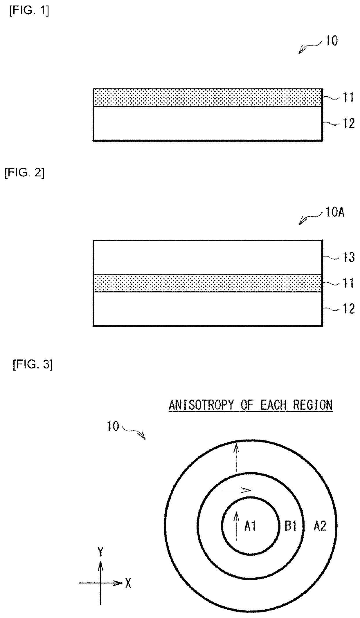
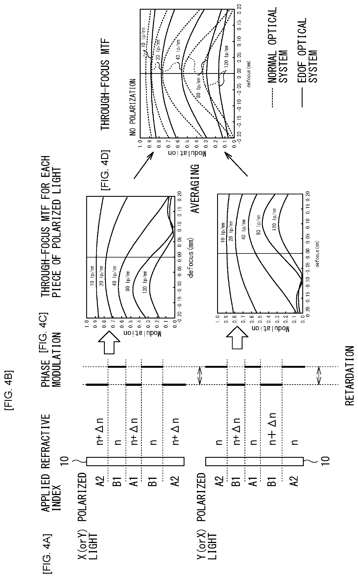
An imaging optical system according to the present disclosure includes: an aperture stop; an image-forming optical system that causes an image to be formed toward an imaging plane of an image sensor; and an optical phase modulator that includes a substance having a birefringence index, and gives two pupil functions to the image-forming optical system. The following conditional expressions are satisfied:1≤(2×L×tan(w)+D) / D<1.4   (1)λ / 4*0.75<Re<λ / 4*1.1   (2), whereL: a distance between the aperture stop and the optical phase modulator; D: an aperture diameter (diameter) of the aperture stop; w: a maximum angle of incidence of a principal light ray that enters the aperture stop; λ: a wavelength of light; and Re: phase retardation caused by birefringence of the optical phase modulator.

Description

TECHNICAL FIELD[0001]The present disclosure relates to an imaging optical system and an imaging apparatus that make it possible to extend a depth of field.BACKGROUND ART[0002]Various techniques of extending a depth of field have been proposed (see PTLs 1 to 4).CITATION LISTPatent Literature[0003]PTL 1: Japanese Unexamined Patent Application Publication No. 2015-5919[0004]PTL 2: Japanese Unexamined Patent Application Publication No. 2018-101065[0005]PTL 3: Japanese Unexamined Patent Application Publication No. 2010-271689[0006]PTL 4: U.S. Unexamined Patent Application Publication No. 2012 / 0281280SUMMARY OF THE INVENTION[0007]Although medical imaging equipment, for example, is demanded to be increased in resolution, the increase in resolution can cause a decrease in a depth of field.[0008]It is desirable to provide an imaging optical system and an imaging apparatus that make it possible to extend a depth of field while suppressing a decrease in resolution performance.[0009]An imaging ...

Claims


Application Information

Patent Timeline
IPC IPC(8): A61B1/00A61B1/05G02B5/30G02B13/02
CPCA61B1/000095A61B1/05A61B1/00188G02B5/3083G02B13/02G02B23/2423G02B5/005G02B21/0012G02B21/361G02B21/22G02B27/0075G02B23/26
Inventor KIKUCHI, NAOMICHINAKAYAMA, MIKI
Owner SONY CORP
Learn More