Needle assembly having needle shield and plug

a technology of needle shield and needle, which is applied in the direction of intravenous devices, infusion needles, other medical devices, etc., can solve the problems of discomfort, inability to prevent dripping from the needle, and dislike the thought of having an injection needle inserted through the skin

Pending Publication Date: 2022-10-27
NOVO NORDISK AS
View PDF0 Cites 0 Cited by
  • Summary
  • Abstract
  • Description
  • Claims
  • Application Information

AI Technical Summary

Benefits of technology

[0010]It is an object of the invention to eliminate or reduce at least one drawback of the prior art, or to provide a useful alternative to prior art solutions.
[0011]In particular, it is an object of the invention to provide a solution which prevents an injection needle from dripping following removal from the skin.
[0012]It is a further object of the invention to provide a relatively simple and inexpensive solution whereby an injection procedure can be paused, with no or only insignificant loss of drug, to allow repositioning of the injection needle.

Problems solved by technology

However, many people dislike the thought of having an injection needle inserted through the skin.
They do not, however, prevent dripping from the needle which may occur if the needle is removed from the skin before the dose expelling mechanism, especially the cartridge piston, has undergone complete relaxation.
It sometimes happens that a person experiences discomfort during an injection, for example due to pressure build-up in the skin from administration of a large liquid volume or due to the injection being performed too close to a nerve or a previous injection site.
Neither is desirable, the latter especially not if the drug is expensive or difficult to obtain.
A halting of the piston actuation mechanism is, however, not immediately possible with simple actuator solutions such as those typically preferred in connection with disposable single shot devices to keep the manufacturing costs at an acceptable level.

Method used


Image

  • Needle assembly having needle shield and plug
  • Needle assembly having needle shield and plug
  • Needle assembly having needle shield and plug

Examples


Embodiment Construction

[0060]When / If relative expressions, such as “upper” and “lower”, “left” and “right”, “horizontal” and “vertical”, “clockwise” and “counter-clockwise”, etc., are used in the following, these refer to the appended figures and not necessarily to an actual situation of use. The shown figures are schematic representations for which reason the configuration of the different structures as well as their relative dimensions are intended to serve illustrative purposes only.

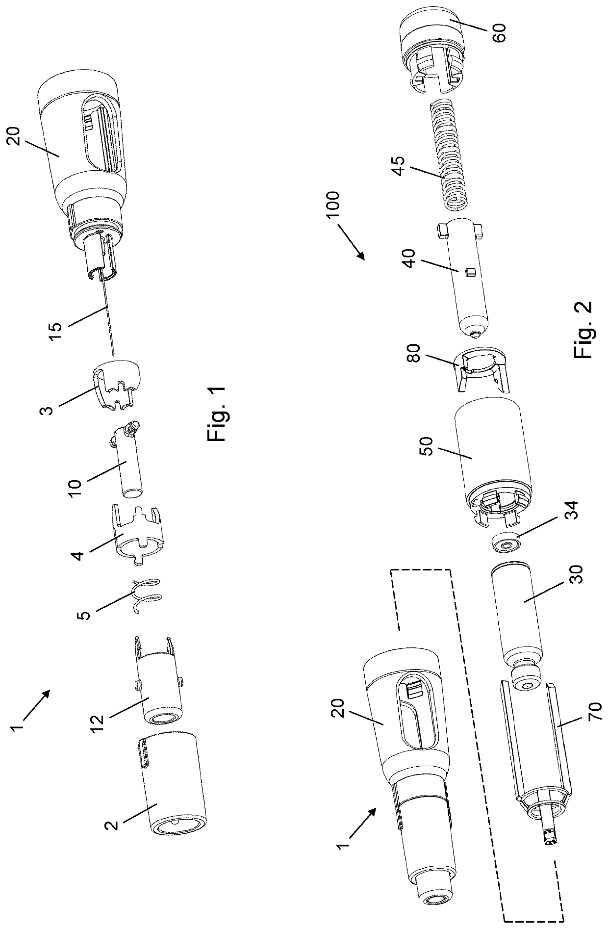
[0061]FIG. 1 is an exploded view of a needle assembly 1 according to an exemplary embodiment of the invention. The needle assembly 1 comprises a cartridge holder 20 in which an injection needle 15 is fixedly mounted, a track sleeve assembly in the form of an inner track sleeve 3, an intermediate track sleeve 4, and an outer track sleeve 2, a needle shield 12, a shield spring 5 in the form of a small compression spring, and a plug 10. The injection needle 15 is a straight tubing extending along a reference axis, and the plug...


PUM


Abstract

The present invention provides a needle assembly (1) for a drug delivery device, comprising a needle hub (25) in which a needle (15) is fixedly mounted, the needle (15) extending along a reference axis and comprising a needle body with a lumen and a distal needle end portion adapted for insertion through a skin layer, a needle shield (12) axially displaceable relative to the needle hub (25) between an extended position in which the distal needle end portion is covered and a retracted position in which the distal needle end portion is exposed, the nee-dle shield (12) being biased towards the extended position, and an elastomeric plug member (10) fitted tightly around a portion of the needle (15), the plug member (10) comprising a self-sealing front section (10.4) and being axially displaceable along the needle body be-tween a proximal plug position in which the distal needle end portion is exposed and a distal plug position in which the distal needle end portion is covered and the lumen is sealed by the self-sealing front section (10.4), wherein the needle shield (12) and the plug member (10) comprise mutually interactable engagement members (12.1, 12.4, 10.5) configured to ensure displacement of the plug member (10) from the proximal plug position to the distal plug position in response to a displacement of the needle shield (12) from the retracted posi-tion to the extended position.

Description

FIELD OF THE INVENTION[0001]The present invention relates to needle assemblies for drug injection devices.BACKGROUND OF THE INVENTION[0002]Parenteral drug administration carried out using a traditional vial and syringe system is increasingly being substituted by administration using a pen injection device. Pen injection devices are particularly convenient in that they allow the user to perform a dosed injection from a prefilled drug reservoir without first having to manually transfer the particular dose from one reservoir (the vial) to another (the syringe).[0003]Predominantly, two types of pen injection devices are available, durable injection devices being capable of delivering one or more doses of drug from a prefilled drug cartridge which can be loaded into the device before use and replaced after exhaustion, and disposable injection devices being capable of delivering one or more doses of drug from a prefilled and non-exchangeable drug cartridge. Each of these types of pen inje...

Claims


Application Information

Patent Timeline
Patent Type & Authority Applications(United States)
IPC IPC(8): A61M5/32A61M5/20A61M5/24
CPCA61M5/3272A61M5/326A61M5/3204A61M5/2053A61M5/2466A61M5/2033A61M2205/0205A61M2005/311A61M5/3158A61M2005/2013A61M2005/3247A61M2005/2073A61M5/3271A61M5/3286A61M5/3293A61M2005/247
Inventor BENGTSSON, HENRIK
Owner NOVO NORDISK AS
Why Eureka
Try Eureka