Rotating electrical machine
a technology of rotating electrical machines and rotating rods, which is applied in the direction of dynamo-electric machines, electrical apparatus, and control/drive circuits. it can solve the problems of air gap, sintered magnets face drawbacks, and sintered magnets are usually at risk of significant production errors, so as to reduce the size of the clearance, reduce the protrusion of the magnet, and reduce the leakage of magnetic flux
- Summary
- Abstract
- Description
- Claims
- Application Information
AI Technical Summary
Benefits of technology
Problems solved by technology
Method used
Image
Examples
first embodiment
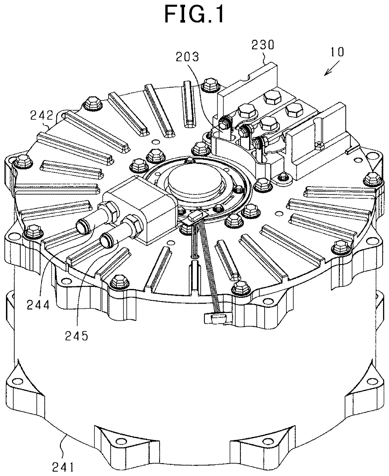
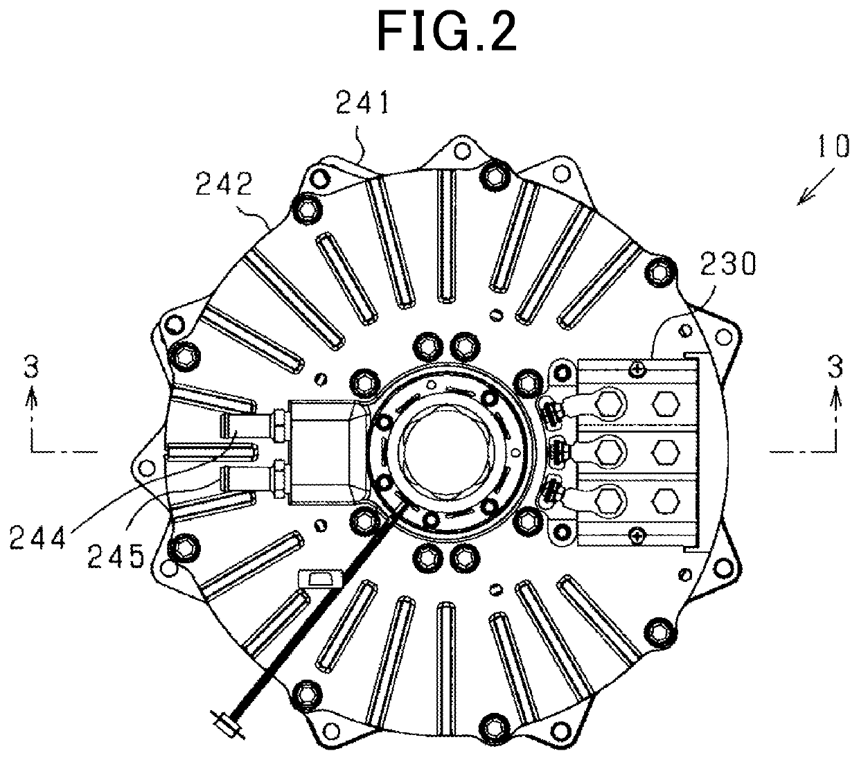
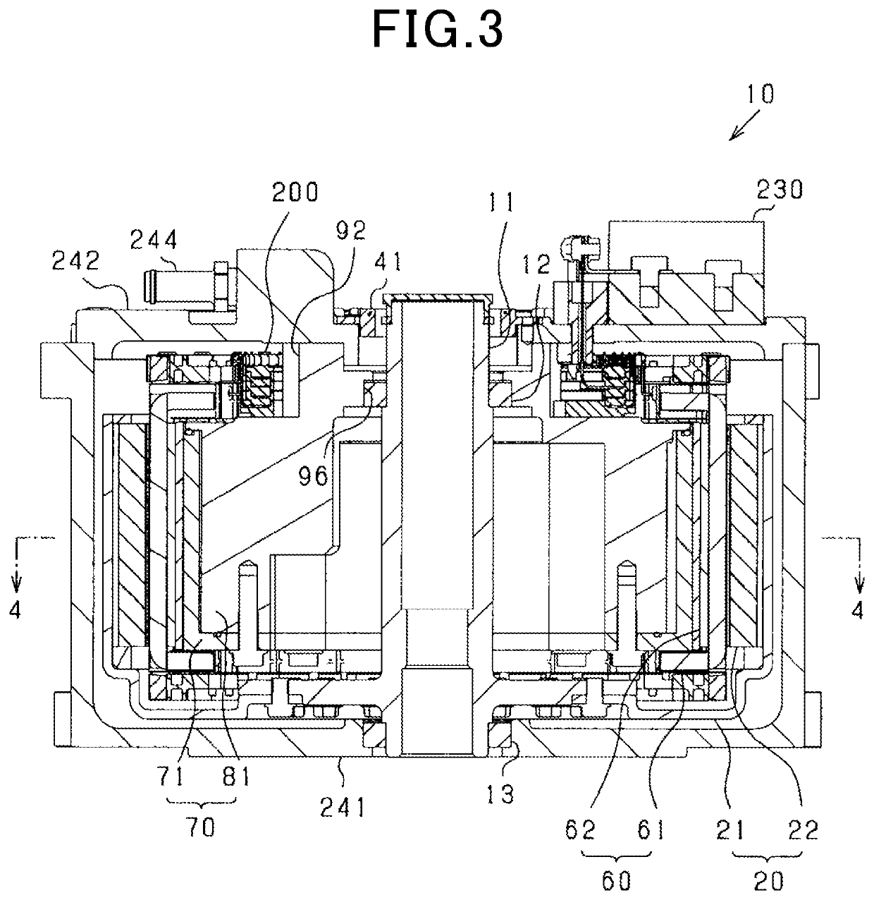
[0066]The rotating electrical machine 10 in this embodiment is a synchronous polyphase ac motor having an outer rotor structure (i.e., an outer rotating structure). The outline of the rotating electrical machine 10 is illustrated in FIGS. 1 to 5. FIG. 1 is a perspective longitudinal sectional view of the rotating electrical machine 10. FIG. 2 is a plan view of the rotating electrical machine 10. FIG. 3 is a longitudinal sectional view (i.e., sectional view taken along the line III-III in FIG. 2) of the rotating electrical machine 10. FIG. 4 is a transverse sectional view (i.e., sectional view taken along the line IV-IV in FIG. 3) of the rotating electrical machine 10. FIG. 5 is an exploded view of component parts of the rotating electrical machine 10. In the following discussion, a direction in which the rotating shaft 11 of the rotating electrical machine 10 extends will be referred to as an axial direction. A direction extending radially from the center of the rotating shaft 11 wi...
second modification
[0243]The magnet unit in each of the first embodiment and the above-described first modification may be designed to have structures described below. The following discussion will mainly refer to structural elements of the magnet unit 70 which are different from those in the first embodiment and the first modification. The rotating electrical machine 10 in the second modification has substantially the same structure as that in the first embodiment.
[0244]The magnet unit 700, as clearly illustrated in FIG. 41, includes the hollow cylindrical magnet holder 31, a plurality of magnets 710 and 720 firmly attached to an inner periphery of the magnet holder 31, and the end plate 33 secured to one of axially opposed ends of the rotor carrier 21 which is located away from the end plate 24. The magnet holder 31 has the same dimension as those of the magnets 710 and 720 in the axial direction of the magnet unit 700. The magnets 710 and 720 have outer peripheries surrounded by the magnet holder 3...
third modification
[0267]The layout of the magnets 710 and 720 described in the second modification may be changed in the following way. The following discussion will mainly refer to structural parts different from those in the second modification.
[0268]When the magnets 710 and 720 are mounted in the magnet holder 31 as in the second modification, it will cause, as illustrated in FIG. 42, the d-axis ends of the stator-facing peripheral surfaces 711 and 721 of the magnets 710 and 720 to slightly protrude toward the stator winding 61. In other words, the d-axis ends of the stator-facing peripheral surfaces 711 and 721 are arranged closer to the stator winding 61 than the q-axis ends of the stator-facing peripheral surfaces 711 and 721 are, thereby resulting in a decreased size of air gaps between the d-axis ends and the stator winding 61 as compared with that between the q-axis ends and the stator winding 61. Such a decrease in size of the air gaps will result in a desirable decrease in amount of leakag...
PUM
 Abstract
Description
Claims
Application Information
 - R&D
- Intellectual Property
- Life Sciences
- Materials
- Tech Scout
- Unparalleled Data Quality
- Higher Quality Content
- 60% Fewer Hallucinations
Browse by: Latest US Patents, China's latest patents, Technical Efficacy Thesaurus, Application Domain, Technology Topic, Popular Technical Reports.
© 2025 PatSnap. All rights reserved.Legal|Privacy policy|Modern Slavery Act Transparency Statement|Sitemap|About US| Contact US: help@patsnap.com


