
Touch display and Anti-interference method thereof

a technology of touch display and anti-interference, applied in the field of displays, can solve the problems of display effect, likely to occur, and reduce the penetration rate of the panel

Active Publication Date: 2022-10-06
SHENZHEN CHINA STAR OPTOELECTRONICS SEMICON DISPLAY TECH CO LTD
View PDF2 Cites 0 Cited by
  • Summary
  • Abstract
  • Description
  • Claims
  • Application Information

AI Technical Summary

Benefits of technology

The present application provides a touch display and an anti-interference method to resolve the problem of noise interference in in-cell touch screens. The method compensates for the interference by a circuit that filters out interfered signals and retains the real touch sensing signals, resulting in improved signal-to-noise ratios and improved touch screen performance.

Problems solved by technology

However, adding a shielding layer will not only reduce a penetration rate of the panel, but at the same time, due to presence of a grid of the shielding layer, a moire pattern is likely to occur, which affects a display effect.
Therefore, problems that the existing in-cell touch screen is seriously interfered by noise need to be solved.

Method used


Image

  • Touch display and Anti-interference method thereof
  • Touch display and Anti-interference method thereof
  • Touch display and Anti-interference method thereof

Examples


Embodiment Construction

[0034]Descriptions of the following embodiments refer to additional drawings to illustrate specific embodiments that can be implemented in the present application. Directional terms mentioned in this application, such as [upper], [lower], [front], [back], [left], [right], [inner], [outer], [side], etc., refer to directions of the attached drawings. Therefore, the directional term used is to illustrate and understand this application, not to limit this application. In the figure, units with similar structures are indicated by the same reference numerals.

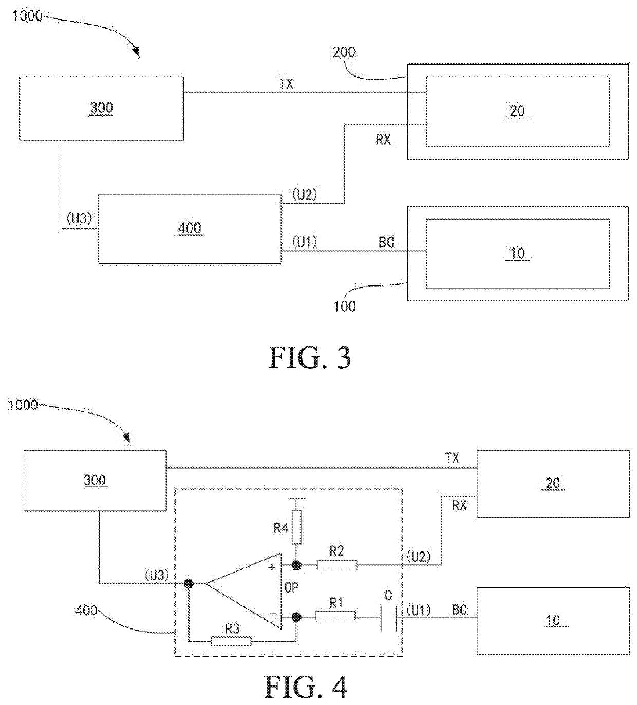
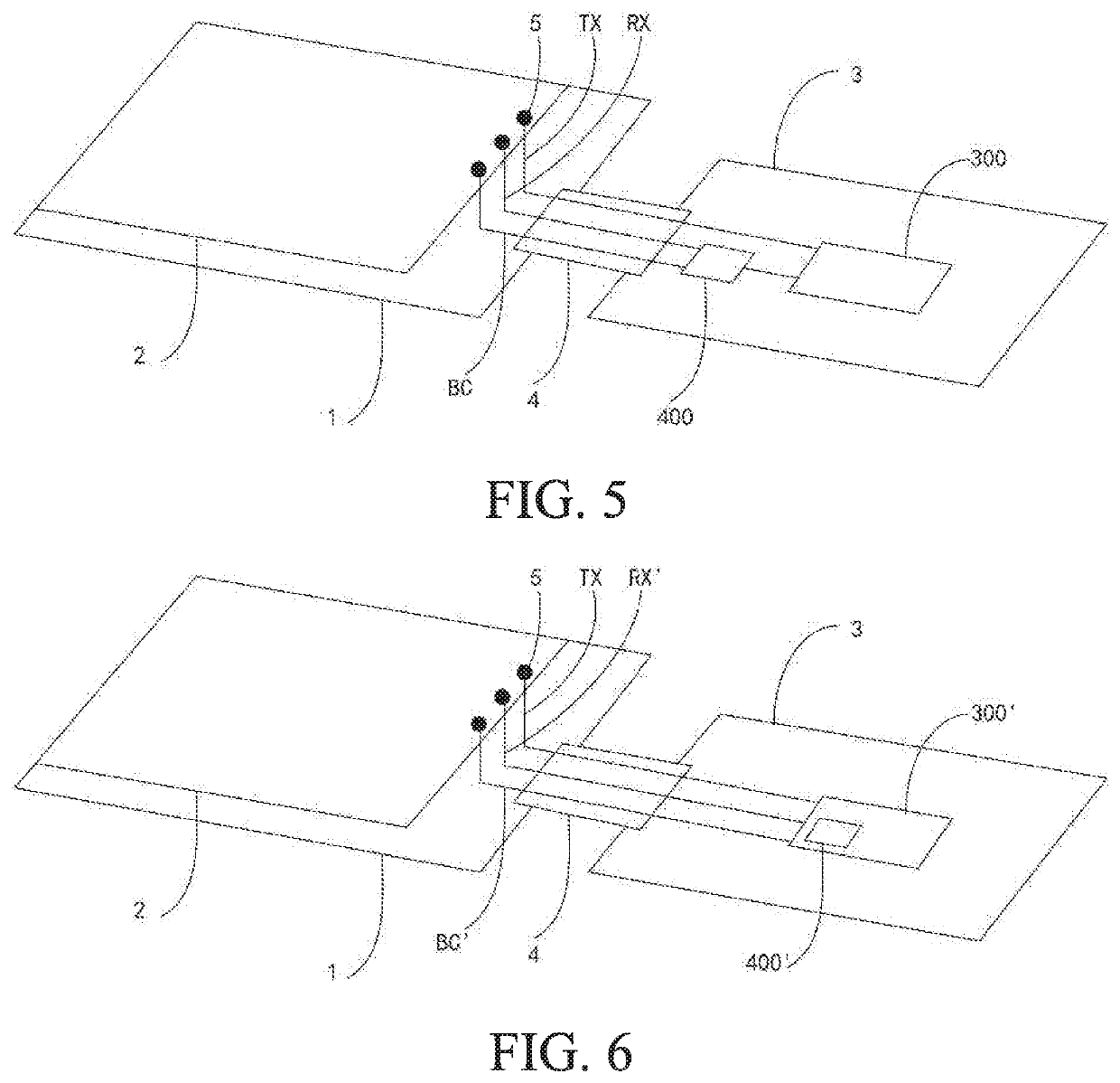
[0035]In an embodiment, as shown in FIG. 3, a touch display 1000 is provided and comprises: a display panel 100; a touch panel 200 disposed on the display panel 100; a touch chip 30; and a compensation circuit 400. The display panel 100 comprises a common electrode layer 10, and the common electrode layer 10 leads to at least one compensation signal line BC. The touch panel 200 comprises a touch layer 20 disposed above the common elec...


PUM


Abstract

A touch display and an anti-interference method thereof are provided. The touch display has a display panel, a touch panel, a touch chip, and a compensation circuit. A compensation signal line is led out from a common electrode layer of the display panel. A sensing signal line is led out from a touch layer of the touch panel. An input terminal of the compensation circuit is connected to the compensation signal line and the sensing signal line, and a compensated sensing signal is output to the touch chip from the output terminal. An ability of the touch screen to resist noise interference is improved.

Description

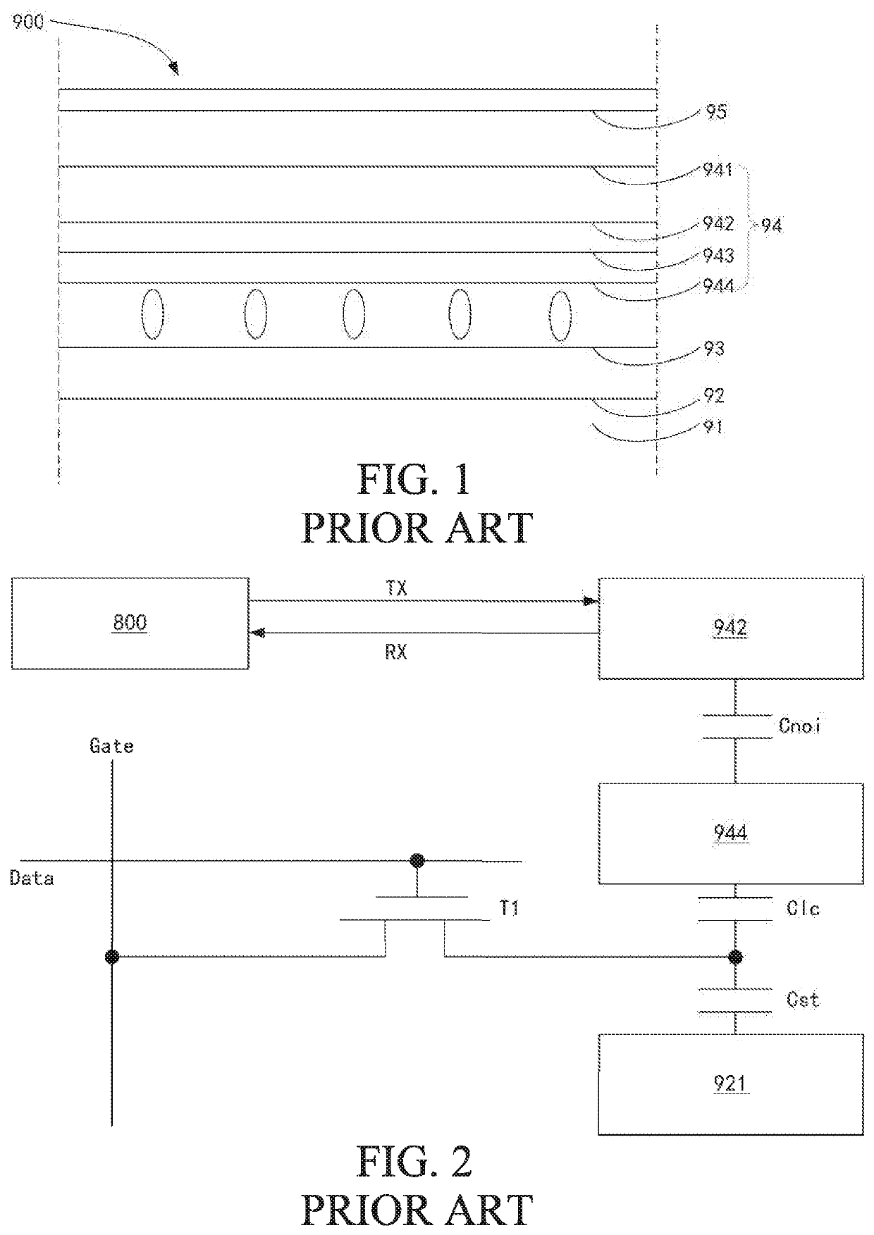
FIELD OF DISCLOSURE[0001]The present application relates to displays, and more particularly to a touch display and an anti-interference method thereof.BACKGROUND OF DISCLOSURE[0002]With a continuous development of capacitive touch screens towards thinner, larger size, and higher precision, an appearance of in-cell touch screens has greatly reduced thickness of display screens. The liquid crystal display 900 shown in FIG. 1 adopts an in-cell touch screen, including a lower polarizer 91, an array substrate 92, a liquid crystal layer 93, a color filter substrate 94, and an upper polarizer 95. The color filter substrate 94 includes a glass substrate 941, a touch layer 942, a color filter layer 943, and a common electrode layer 944. The touch layer 942 is directly fabricated on the color filter substrate 94 in the liquid crystal display 900. However, a distance between the touch layer 942 and a driving component (such as the common electrode layer 944) in the liquid crystal display 900 i...

Claims


Application Information

Patent Timeline
IPC IPC(8): G06F3/041G06F3/044G06F3/045
CPCG06F3/0412G06F3/0445G06F3/045G06F3/0418G06F3/044G06F3/04164
Inventor DAI, AIMINZHAO, HAO
Owner SHENZHEN CHINA STAR OPTOELECTRONICS SEMICON DISPLAY TECH CO LTD
Learn More