
Construction apparatus and method for lifting and sliding object over barrier in horizontal direction

a construction apparatus and horizontal direction technology, applied in the direction of load-engaging elements, cranes, transportation and packaging, etc., can solve the problems of high construction cost, long construction period, high construction quality, etc., and achieve high automaticity, stable structure, and improved environmental condition of manual operation

Active Publication Date: 2016-03-08
GUANGZHOU DI ER CONSTR & ENG CO LTD +1
View PDF17 Cites 3 Cited by
  • Summary
  • Abstract
  • Description
  • Claims
  • Application Information

AI Technical Summary

Benefits of technology

This solution stabilizes the lifting process, reduces safety hazards, improves working conditions, and significantly shortens construction time while ensuring quality and safety, transforming labor-intensive construction methods into more efficient and advanced technology-driven approaches.

Problems solved by technology

With the development of society, and the increase of labor cost, negative influence of traditional construction model shows all the time, that is, high-altitude working has much potential risk and long construction period, whose construction quality is very hard to be guaranteed and project cost stays at a high level.
(1) Large quantity of high-altitude working, high safety hazard, and difficulty to carry out the safety protection;
(2) Bad environment condition for welding as high-altitude working, which makes it hard to guarantee construction quality;
(3) Large quantity of high-altitude working, bad operational environment condition for welding as high-altitude working, which lead to an inconvenient operation and long construction period on site.

Method used


Image

  • Construction apparatus and method for lifting and sliding object over barrier in horizontal direction
  • Construction apparatus and method for lifting and sliding object over barrier in horizontal direction
  • Construction apparatus and method for lifting and sliding object over barrier in horizontal direction

Examples


Embodiment Construction

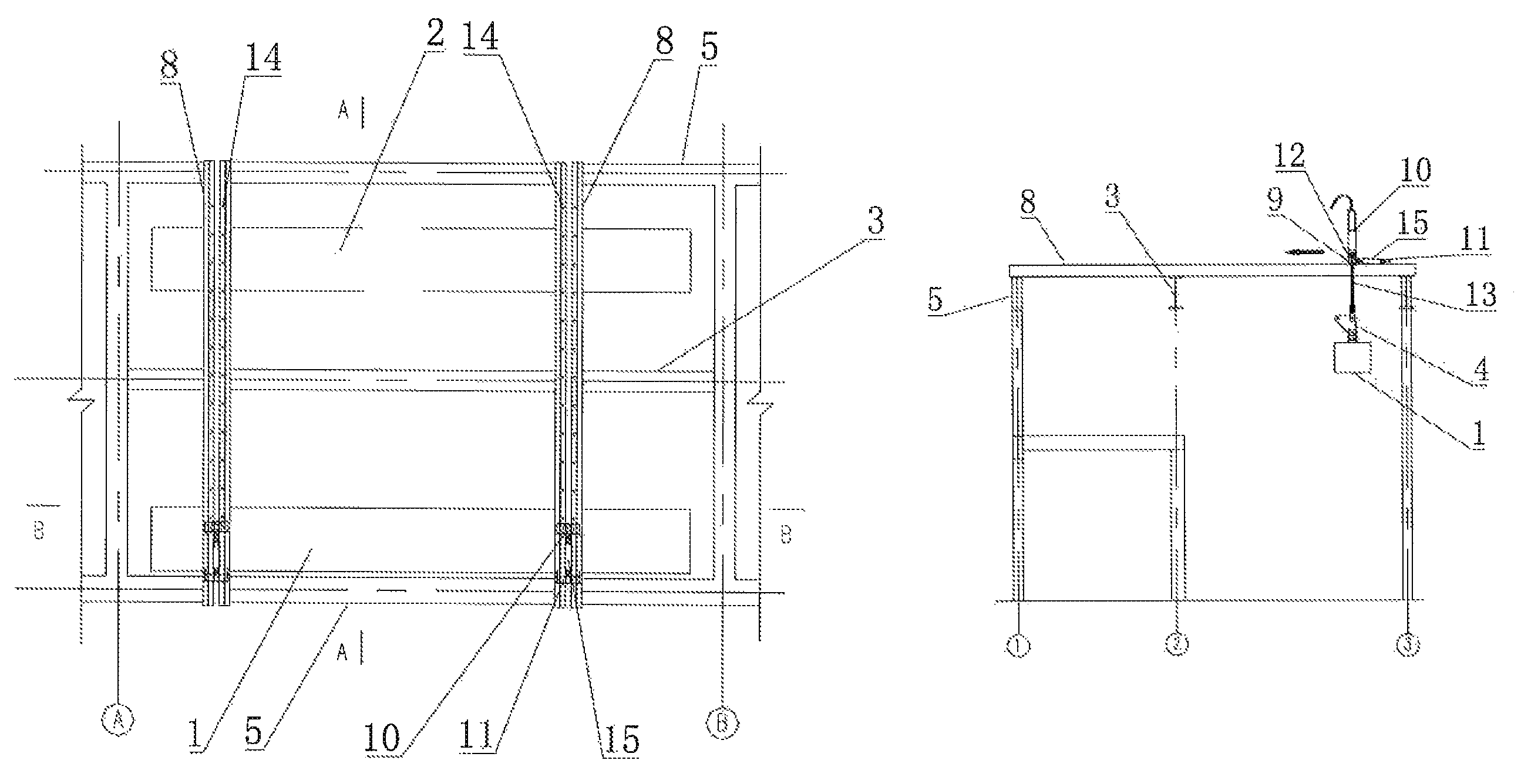
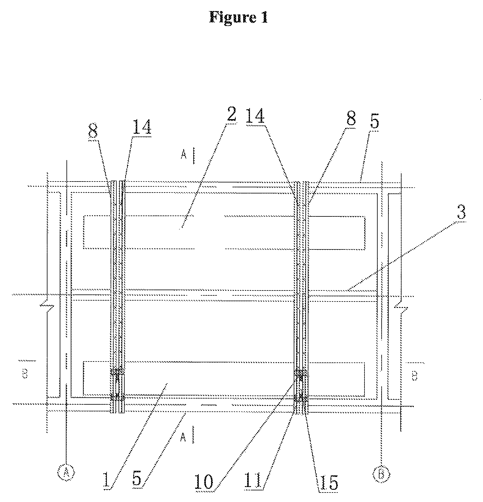
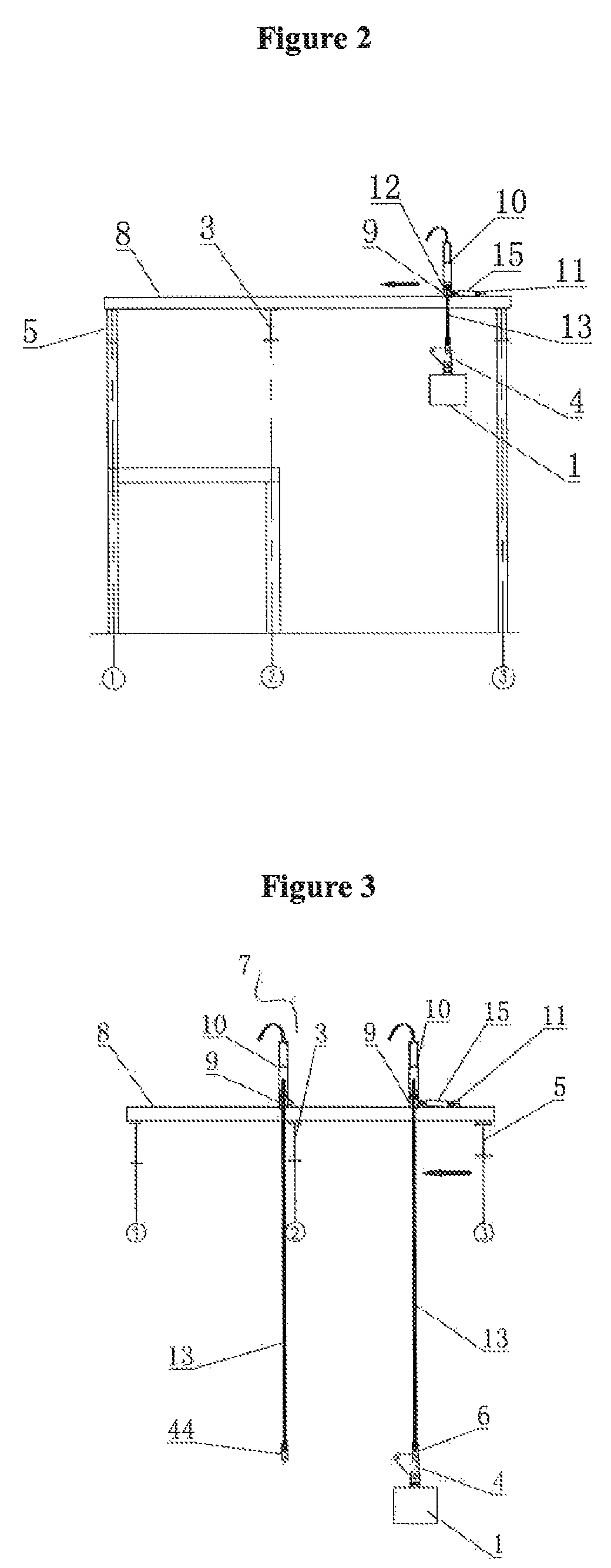
[0082]As shown in FIGS. 1 to 7, a construction apparatus for lifting and sliding object over barrier in horizontal direction according to the present invention, comprising at least two lifting beams 8 that placed on supporting structures 5 and located above barrier 3, a push instrument kit 15, shoulder beams 9 and lifter 10 installed on each shoulder beam 9. A plurality of bolt-holes 14 are configured at interval regularly on upper surface of the lifting beam 8, the interval between two adjacent bolt-holes 14 should match with each pace of the hydraulic push instrument kit 15.

[0083]The hydraulic lifter 10 is welded onto the shoulder beam 9, the hydraulic push instrument kit 15 is installed on each lifting beam 8, the push instrument kit 15 comprises a head connected to ear-plate 92 of the shoulder beam 9, a push instrument body, and a base 11 used to sustain the body 15. The base 11 can be fixed to the lifting beam 8 by bolts through the bolt-holes 14 configured on upper surface of ...


PUM


Abstract

The present invention disclosed an apparatus and for lifting and sliding object over barrier in horizontal direction, comprising two lifting beams that placed on supporting structures and located above object to be lifted and a barrier, and a lifter installed on the lifting beam. A hydraulic push instrument kit is installed on a lifting beam to move the shoulder beam and the lifter. The lifter connects with the object through the steel strand and a triangle transfer connector having three fixed-holds. When the steel strand encounters a barrier in horizontal direction, setting another lifting apparatus on the part of lifting beams located on the other side of the barrier, connecting another lifting apparatus with the third fixed-hold of transfer connectors 4 by steel strands, and lifting the object until whole load of the object has been transferred onto the second lifter and the object can move to the desired position.

Description

CROSS REFERENCE TO RELATED APPLICATIONS[0001]This application claims priority of Application No. CN 201310194901.4 filed in China on May 23, 2013, under 35 U.S.C. §119, the entire contents of which are hereby incorporated by reference.FIELD OF TECHNOLOGY[0002]The present invention relates to a field about construction apparatus of civil engineering, and in particular a construction apparatus and method for lifting and sliding object over barrier in horizontal direction.BACKGROUND OF THE INVENTION[0003]With the development of society, and the increase of labor cost, negative influence of traditional construction model shows all the time, that is, high-altitude working has much potential risk and long construction period, whose construction quality is very hard to be guaranteed and project cost stays at a high level.[0004]Therefore construction method of lifting integrally transforms high-altitude working into ground operation, which greatly reduces potential safety hazard, improves w...

Claims


Application Information

Patent Timeline
Patent Type & Authority Patents(United States)
IPC IPC(8): B66C19/00B66C13/08B66C13/04
CPCB66C13/08B66C13/04
Inventor GAO, JUNYUEWANG, LONGWEI, WEIWEN, JIANMINGYIN, SUIJIA, YANFENGZHAO, YUANTAO
Owner GUANGZHOU DI ER CONSTR & ENG CO LTD
Learn More