Endosteal horizontally placed dental implant system and method

a dental implant and endosteal technology, applied in dental implants, dental surgery, medical science, etc., can solve the problems of bone resorption and deterioration, tooth loss is a problem experienced by millions of adults, loose or ill-fitting dentures, etc., and achieve the effect of wide versatility

Pending Publication Date: 2022-08-25
WASSEF MICHAEL
View PDF10 Cites 0 Cited by
  • Summary
  • Abstract
  • Description
  • Claims
  • Application Information

AI Technical Summary

Benefits of technology

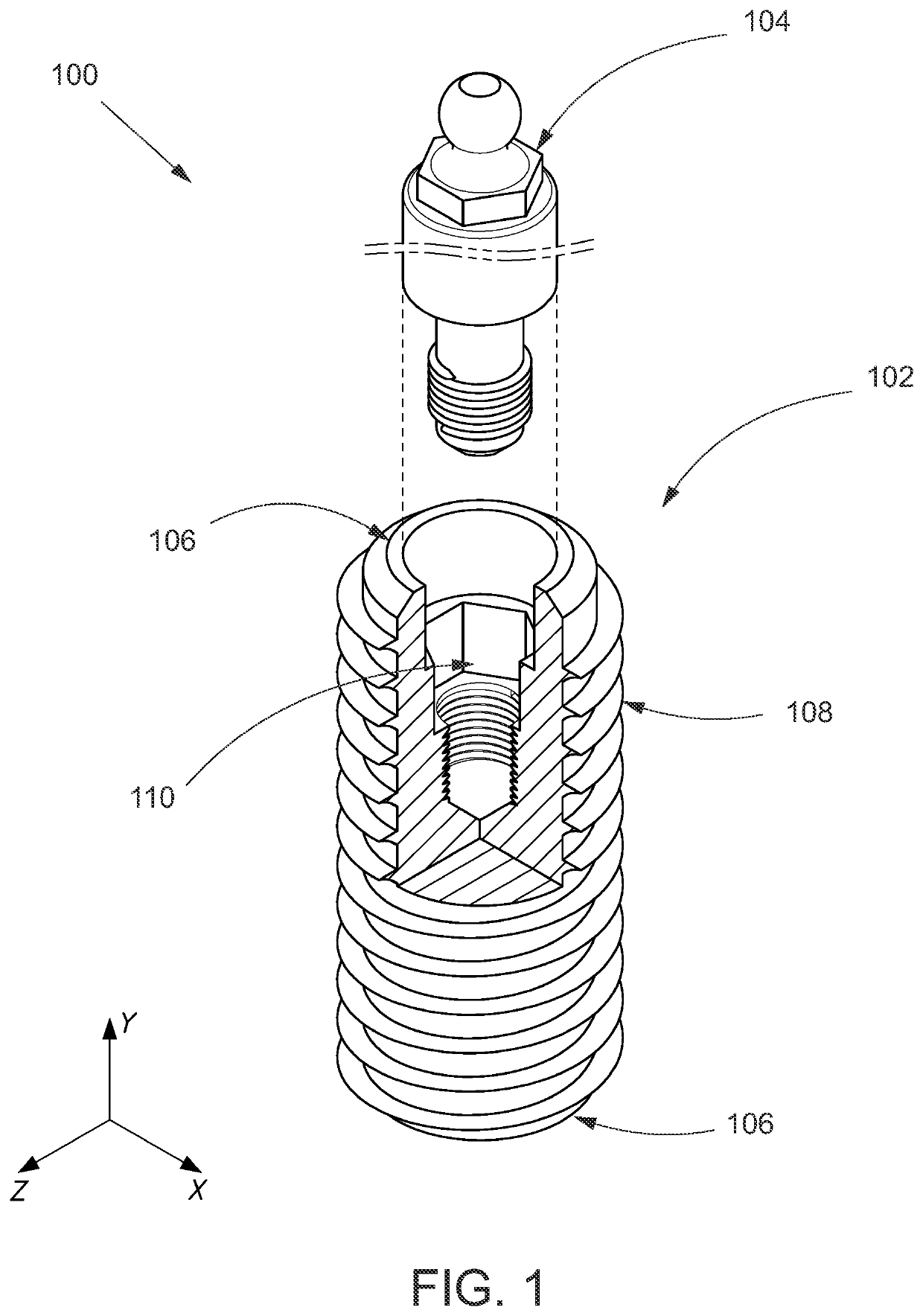
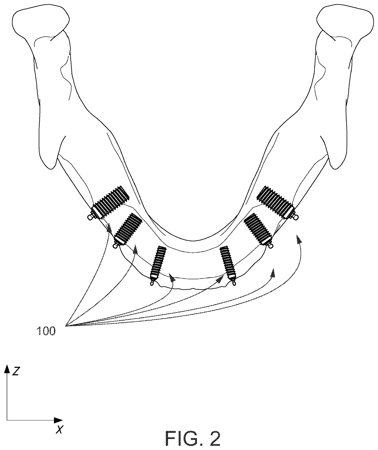
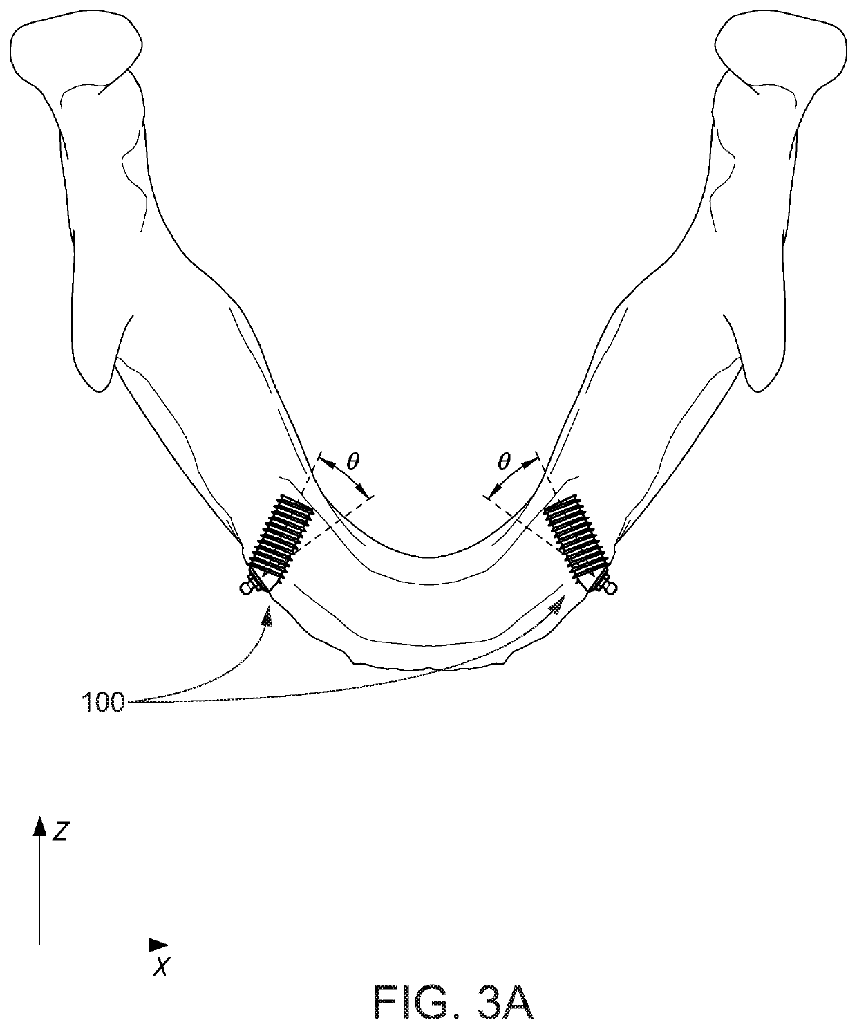
[0017]The invention in general includes a circular, cylindrical shaped metal alloy dental implant which is placed in the jaw(s) through a horizontal access preparation. The implants' diameters, radii, width, height, length, internal and external retentive architecture will vary depending on what the existing jaw morphology of the patient dictates. The invention will be geared to help patients who are not candidates for traditionally placed implants, by changing the design of traditional dental implants and placing the implants horizontally. By changing the placement dynamics of the implant, one also, without exception, vastly changes the physics of the mechanism of the implant / prosthetic mechanism. The horizontally placed dental implants are designed to successfully utilize otherwise seemingly unusable bone.
[0018]An object of the invention is to enable people who are not candidates for traditional implants (due to lack of bone volume, width, height or any combination of the three); to be able to obtain dental implants through non-traditional techniques of placement. Such a system and method would allow for a greater number of dental implant candidates. Persons currently suffering bone loss and loose dentures; would have a substantially improved quality of life.
[0021]The horizontally placed dental implant system can also include a retractable “retentive arm” that extends from the center of the implant and into the oral cavity when activated. The retentive arm or arms can be configured to extend from the center of the circular implant, to both the cheek, and tongue areas of the mouth. The retentive arm can be a rigid structure, or the retentive arm can be made of a flexible material so as to offer movement depending on patient need; it may also be a combination of partially rigid and partially flexible materials on the same retentive arm. In one embodiment of the invention, the retentive arm can allow for mechanical activation via a specific tool that will result in the extension of the retentive arm, or arms. In alternative embodiments, a depressible activation may be employed. In alternative embodiments the implant may have varying internal architecture and design which will allow for rotational, and / or lateral movement of the retentive arm; this is in an effort to decrease the stress load on the retentive arm and / or implant fixture. The movements may be fully directional, in any direction on a 360-degree axis.
[0025]It must be further understood that numerous dentures and prostheses, either full or partial, can be successfully attached to the horizontally placed implant system. Such a system offers a wide degree of versatility for patients lacking the crestal bone height for traditional crestal approach dental implants and techniques.

Problems solved by technology

Tooth loss is a problem experienced by millions of adults.
Total edentulism is typically the result of progressive and prolonged lack of dental care but can be also caused by trauma.
Many of these patients have, or will have, loose or ill-fitting dentures.
Over time, this lack of stimulation causes the bone to resorb and deteriorate.
Because traditional dentures and bridges rely on the jaw bones to hold them in place, people suffering bone loss often experience loosening of their dentures and problems eating and speaking.
Eventually, bone loss may become so severe that dentures cannot be held in place even with strong adhesives, and a new set may be required.
Though proper denture care, repair, and refitting are essential to maintaining oral health, bone loss may still occur.
Fabricating a new prosthesis for patients suffering from bone atrophy is not a guarantee that the new prosthesis will sufficiently solve their problems regarding a “loose fitting” or mobile denture; as the core cause for having loose dentures is not corrected, which is loss of bone volume and / or width and / or height.
Biologic complications are disturbances in the implant function characterized by biological processes affecting the supporting peri-implant tissues, namely, early and late implant failures, and adverse reactions in the peri-implant hard and soft tissues.
Technical complications refer to mechanical damage of the implant, implant components and / or prosthesis.
The maxilla and mandible present very different surgical and restorative challenges because of bone quality and quality, ridge morphologic and resorptive patterns, location of anatomic structures, and biomechanical considerations.
Patients who have suffered bone loss, however, may not be suitable candidates for conventional dental implants which are placed in through, and originate from, the crest of the ridge.
Without this requisite osseointegrated surface area of the implant, the implant will fail due to lack of strength and support from the bone (lack of osseointegrated surface area).
Because of bone loss, there is oftentimes not enough bone in the maxilla and / or mandible to crestally insert dental implants into the mandible and maxilla, thereby not being able to help the patient retain the partial or complete denture.
Wearing headgear can be uncomfortable, and compliance is sometimes a problem.
And while such implants are useful for temporary purposes, TADS do not provide a permanent system for attaching dental prostheses, retentive elements and / or abutments, they are primarily used for orthodontics, not for restorative dentistry.

Method used


Image

  • Endosteal horizontally placed dental implant system and method
  • Endosteal horizontally placed dental implant system and method
  • Endosteal horizontally placed dental implant system and method

Examples


Embodiment Construction

[0061]Terminology used herein is used for the purpose of describing particular embodiments only, and is not intended to limit the scope of the present invention. It must be understood that as used herein and in the appended claims, the singular forms “a,”“an,” and “the” include the plural reference unless the context clearly dictates otherwise. For example, a reference to “an element” is a reference to one or more elements and includes all equivalents known to those skilled in the art. All conjunctions used are to be understood in the most inclusive sense possible. Thus, the word “or” should be understood as having the definition of a logical “or” rather than that of a logical “exclusive or” unless the context clearly necessitates otherwise. Language that may be construed to express approximation should be so understood unless the context clearly dictates otherwise.

[0062]Unless defined otherwise, all technical and scientific terms used herein have the same meanings as commonly under...


PUM


Abstract

An endosteal horizontally placed non-crestal dental implant system including at least one dental implant having a proximal end, a distal end, an internal architecture, and a helical thread extending along the outside region between the proximal end and the distal end. The one or more implants are configured to be implanted horizontally or near horizontally by way of a non-crestal approach, into a mandible or maxilla and to engage with bone tissue. The system also includes at least one dental implant abutment having a proximal end for attaching to the said dental implant and a distal end configured for the attachment of a dental prosthesis. A method of diagnosis and treatment of edentulism using the endosteal horizontally placed non-crestal dental implant system is also recited.

Description

BACKGROUND OF THE INVENTION1. Technical Field[0001]The invention relates generally to the field of dental implants. More specifically, the present invention relates to a endosteal horizontally placed dental implant system and method.2. Background Art[0002]Edentulism is the condition of having lost one or more teeth. Tooth loss is a problem experienced by millions of adults. Tooth loss may involve one or more teeth by factors ranging from injury to periodontal disease. Since edentulism is irreversible and is often progressive, it is one of the factors that closely mark a decline in a patient's overall state of oral health.[0003]There are two types of edentulism. Partial edentulism means the partial loss of the functional dentition. Stated differently, this means the loss of one or several, but not all teeth. This definition also refers to the loss of functional teeth. Total edentulism refers to the total loss of the functional dentition. Total edentulism is more common in mature and ...

Claims


Application Information

Patent Timeline
Patent Type & Authority Applications(United States)
IPC IPC(8): A61C8/00
CPCA61C8/0053A61C8/001A61C8/0074A61C8/003A61C8/0022A61C8/0018A61C8/005
Inventor WASSEF, MICHAEL
Owner WASSEF MICHAEL
Why Eureka
Try Eureka