Bypass switch

a bypass switch and switch technology, applied in the direction of high-tension/heavy-duty switches, contact, explosion switch closing, etc., can solve the problems of large spring constant (k) of springs, difficult to manufacture, and high cost of springs, so as to reduce the probability of generating noise in firing signals, accurate and stable operation of bypass switches, and large spring coefficients

Pending Publication Date: 2022-08-04
LS ELECTRIC CO LTD
View PDF0 Cites 0 Cited by
  • Summary
  • Abstract
  • Description
  • Claims
  • Application Information

AI Technical Summary

Benefits of technology

The present patent offers an improved design for a bypass switch that provides better insulation, reduces noise, and improves operating speed. The switch includes an insulating cover that separates the power source and a second bus bar, and the actuator part is insulated from the circuit part. This eliminates the need for an external insulation design and reduces the possibility of generating noise in the firing signal. The actuator receives a firing signal based on ground, resulting in an accurate and stable operation. A movable part extension rod is formed in a cylindrical shape to provide space for mounting and operating a contact spring, and a commercially available spring can be used instead of a special spring with a large spring coefficient. This improves contact pressure and reduces the weight of components. The bypass switch also has a faster operating speed and facilitates stroke control for the movable contact.

Problems solved by technology

This causes a limit in an installation space of the spring 48, and thereby it is difficult to exert sufficient contact pressure.
A spring having a large spring constant (k) is not only difficult to be manufactured, but also expensive.
In addition, when a spring having a large spring constant is used, a small deformation (Δx) causes a great change in contact pressure force (F=k×Δx), which makes it difficult to control the stroke of the movable contact 21 of the bypass switch.

Method used


Image

  • Bypass switch
  • Bypass switch
  • Bypass switch

Examples


Embodiment Construction

[0056]Hereinafter, preferred implementations of the present disclosure will be described with reference to the accompanying drawings, so that a person skilled in the art can easily carry out the disclosure. It should be understood that the technical idea and scope of the present disclosure are not limited to those preferred implementations.

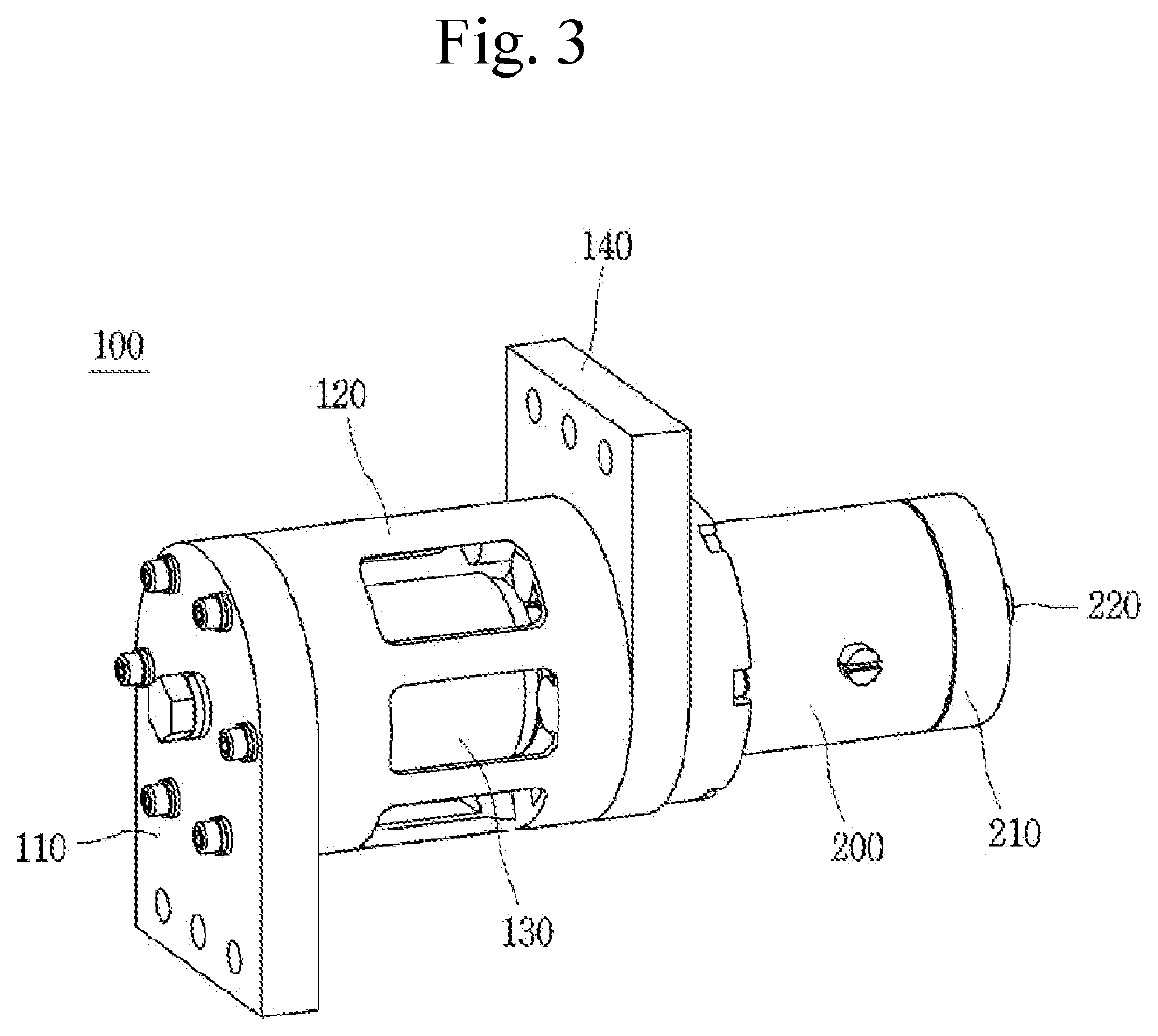
[0057]FIG. 3 is a perspective view of a bypass switch for an HVDC transmission module in accordance with one implementation of the present disclosure, and FIG. 4 is an exploded perspective view of FIG. 3. Hereinafter, a bypass switch in accordance with each implementation of the present disclosure will be described in detail with reference to the accompanying drawings.

[0058]In the description of the present disclosure, a direction in which a first bus bar 110 is disposed based on a longitudinal direction of the case 120 may be referred to as a front side (front surface), and a direction in which a second bus bar 140 is disposed is referred to as a...


PUM


Abstract

The present disclosure relates to a bypass switch used in a super-high voltage direct current transmission sub-module including a case; a first bus bar; a second bus bar; a fixing contact provided in a hollow part and connected to the first bus bar; a movable contact provided in the hollow part, and connected to the second bus bar so as to come into contact with or be separated from the fixing contact; an insulating cover coupled to the rear surface of the second bus bar, and having an accommodation part therein; a movable part extension rod provided on the accommodation part and coupled to the movable contact; and an actuator provided on the rear part of the insulating cover, and providing power for moving the movable part extension rod.

Description

TECHNICAL FIELD[0001]The present disclosure relates to a bypass switch, and more particularly, to a bypass switch used in a sub-module of a high voltage direct current (HVDC) transmission system.BACKGROUND ART[0002]In general, a High Voltage Direct Current (HVDC) transmission system is a power transmission facility that AC power generated in a power plant is transmitted after being converted into DC power in a transmission site and the DC power is supplied after being re-converted into AC power in a reception site. When DC transmission is applied, there is an advantage in that transmission loss is greatly reduced compared to AC transmission.[0003]An HVDC transmission system requires converters for converting electricity from AC power into DC power or from DC power into AC power, and these converters include a plurality of sub-modules.[0004]When a failure occurs in some of the plurality of sub-modules, a configuration or device for excluding the failed sub-modules from the transmissi...

Claims


Application Information

Patent Timeline
IPC IPC(8): H01H33/662H01H33/664H01H33/666
CPCH01H33/662H01H33/666H01H33/664H01H33/66207H01H33/6606H01H1/50H01H2033/6665H01H39/004H01H79/00
Inventor LEE, GYEONGHO
Owner LS ELECTRIC CO LTD
Why Eureka
Try Eureka