Tibia intercondylar spine fracture reduction fixing device
A fixation device and intercondylar spine technology, applied in fractures, medical science, etc., can solve the problems of inability to fix the patient's leg, inaccurate and stable surgical operation, etc., to reduce the patient's nervousness, safe and stable operation, and Precise and smooth effect
- Summary
- Abstract
- Description
- Claims
- Application Information
AI Technical Summary
Problems solved by technology
Method used
Image

Examples
Embodiment 1
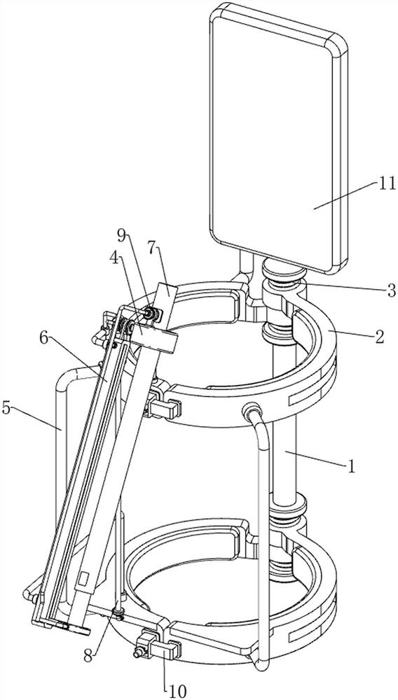
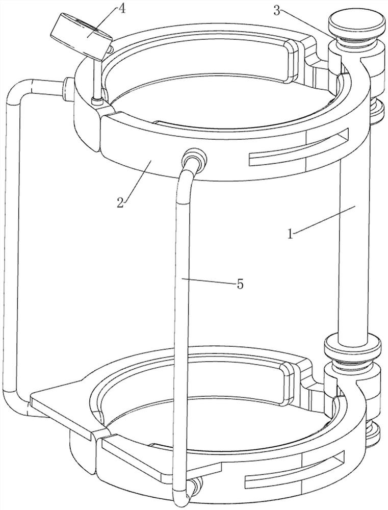
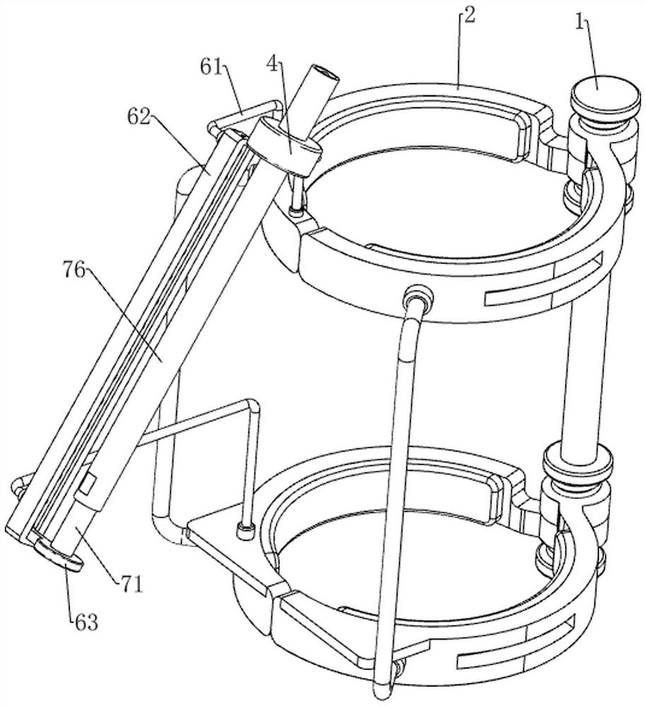
[0038] A kind of tibial intercondylar spine fracture reduction and fixation device, such as Figure 1-9 As shown, it includes a first connecting rod 1, a clamping ring 2, a torsion spring 3, a positioning ring 4, a pull rod 5, a jacking mechanism 6 and a fixing mechanism 7, and the upper and lower sides of the first connecting rod 1 are rotatably sleeved. There is a group of clamping rings 2, and rubber pads are arranged on the inner side of the clamping rings 2, which can play a protective effect. Every two clamping rings 2 form a group, and the two clamping rings 2 of the same group are arranged symmetrically front and back. On the front and rear sides, a tie rod 5 is bolted between the two clamping rings 2 on the same side, and a torsion spring 3 is connected between the clamping ring 2 and the first connecting rod 1, and the torsion spring 3 is wound around the first connecting rod 1. On the outer side, the upper side of the clamping ring 2 at the upper rear is bolted with...
Embodiment 2
[0043] On the basis of Example 1, such as figure 1 , Figure 9 and Figure 10 As shown, a pulling mechanism 8 is also included, and the pulling mechanism 8 includes a connecting pulley 81, a second fixed rod 82, an electric slide rail 83, a second connecting block 84 and a stay rope 85, and the upper part of the sliding rail block 62 is rotatably provided with a connection Pulley 81, the middle part of the first fixed rod 61 above is provided with a second fixed rod 82, and an electric slide rail 83 is installed between the second fixed rod 82 and the lower rear clamping ring 2 by screws, and the electric slide rail 83 is covered with a The second connection block 84, the upper side of the front part of the second connection block 84 is connected with a stay rope 85, the tail end of the stay rope 85 is connected with the first top block 63 through the cooperation of the connecting pulley 81, and the stay rope 85 slides through the slide rail block 62 and return spring 64.
...
Embodiment 3
[0046] On the basis of Example 2, such as figure 1 , Figure 11 and Figure 12 As shown, clamping mechanism 9 is also included, and clamping mechanism 9 includes a third connecting block 91, a second connecting rod 92, a pressure block 93, a second connecting spring 94, a third connecting rod 95 and a push rod 96, positioning The left part of the ring 4 is bolted with a third connecting block 91, the third connecting block 91 slides through a second connecting rod 92, the left side of the second connecting rod 92 is welded with a third connecting rod 95, the third connecting rod 95 bottom It is bent downward, and a second connecting spring 94 is connected between the second connecting rod 92 and the third connecting block 91. The second connecting spring 94 is wound around the outside of the second connecting rod 92, and the left side of the lower part of the hollow sleeve 76 There is a square groove, the second connecting rod 92 is connected with a pressing block 93 capable...
PUM
 Abstract
Description
Claims
Application Information
 - R&D
- Intellectual Property
- Life Sciences
- Materials
- Tech Scout
- Unparalleled Data Quality
- Higher Quality Content
- 60% Fewer Hallucinations
Browse by: Latest US Patents, China's latest patents, Technical Efficacy Thesaurus, Application Domain, Technology Topic, Popular Technical Reports.
© 2025 PatSnap. All rights reserved.Legal|Privacy policy|Modern Slavery Act Transparency Statement|Sitemap|About US| Contact US: help@patsnap.com