Split Lens and Camera Module and Electronic Apparatus
a technology of optical modules and split lenses, applied in the field of split lenses, can solve the problems of difficult fixation or correction of tolerances, less resolution of optical modules, and more challenges in the design and development of optical lenses, so as to improve the performance of split lenses, reduce the overall height of lens groups, and prevent the deformation of conventional spacers
- Summary
- Abstract
- Description
- Claims
- Application Information
AI Technical Summary
Benefits of technology
Problems solved by technology
Method used
Image

Examples
second embodiment
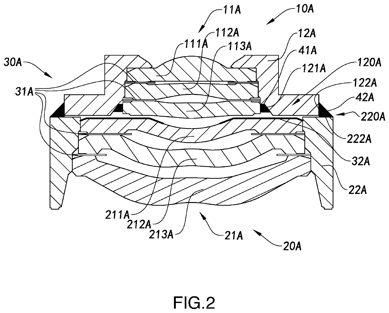
[0081]According to the second preferred embodiment, the split lens comprises four spacing elements 31A. The light shielding element 32A is disposed on a top surface of the fourth lens 211A of the second lens group 20A. In other words, the four spacing elements 31A and one light shielding element 32A constitute the light shielding assembly 30A to collectively form a predetermined light path for the split lens. It is worth mentioning that each of the spacing elements 31A has an annular shape and is made of opaque material. In other words, the spacing elements 31A and the light shielding elements 32A of the light shielding assembly 30A are respectively placed at intervals of the lenses, thereby ensuring optical separation between the lenses, effective light aperture and consistency of the optical axis. One of the spacing elements 31A of the light shielding assembly 30A is disposed between the first lens 111A and the second lens 112A. One of the spacing elements 31A is disposed between ...
third embodiment
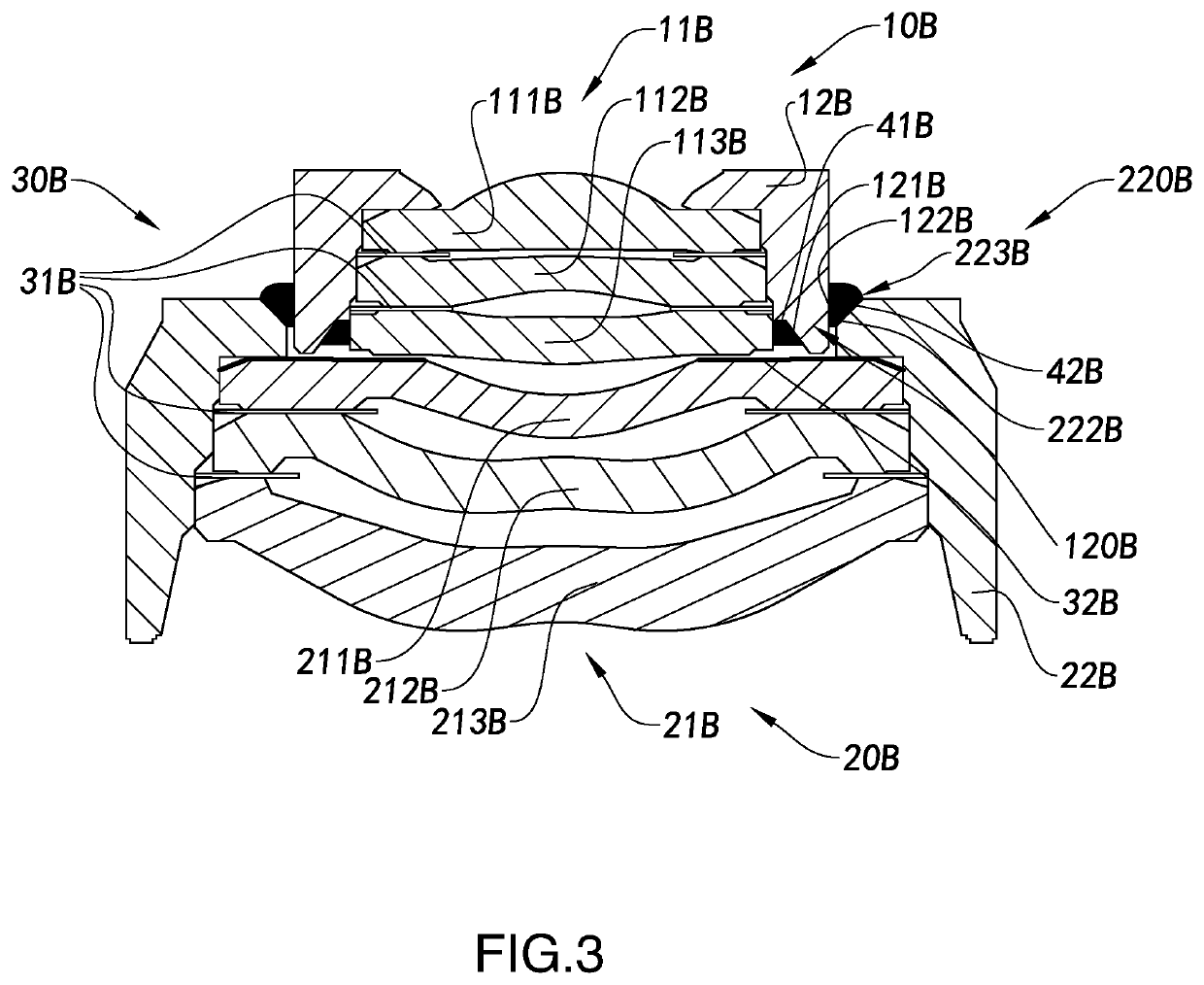
[0087] preferably, the connection between the lens barrels is permanently coupled with each other to form the split lens. The outer retention surface 122B is defined at an outer side of the bottom portion of the first lens barrel 12B, and the outer retention surface 222B of the second retention portion 220B is defined at an inner side of the top portion of the second lens barrel 22B. The second lens barrel 22B further has a retention groove 223B formed at an inner side thereof. Particularly, the retention groove 223B is formed at a top portion of the second lens barrel 22B, wherein the retention groove 223B is formed with an annular shape. In other words, the retention groove 223B is formed at an inner opening rim of the second lens barrel 22B. The retention groove 223B has an inner diameter gradually increased from the second lens group 20B toward the first lens group 10B. The diameter size of the retention groove 223B is configured corresponding to the first outer retention surfac...
fourth embodiment
[0090]FIG. 4 illustrates a split lens according to a fourth preferred embodiment of the present invention, wherein the split lens of the fourth embodiment is constructed to have two lens groups as an example. The first lens set 11C of the first lens group 10C comprises a first lens 111C, a second lens 112C, and a third lens 113C. The second lens set 21C of the second lens group 20C comprises a fourth lens 211C, a fifth lens 212C and a sixth lens 213C. The first lens 111C, the second lens 112C and the third lens 113C are mounted in the first lens barrel 12C. The fourth lens 211C, the fifth lens 212C and the sixth lens 213C are mounted in the second lens barrel 22C.
[0091]According to the fourth embodiment, the light shielding assembly 30C comprises five shielding elements 32A. It is worth mentioning that the light shielding elements 32C are coated on the bottom surfaces of the lenses, wherein each of the light shielding elements 32C is made of an opaque material to prevent light from ...
PUM
 Abstract
Description
Claims
Application Information
 - R&D
- Intellectual Property
- Life Sciences
- Materials
- Tech Scout
- Unparalleled Data Quality
- Higher Quality Content
- 60% Fewer Hallucinations
Browse by: Latest US Patents, China's latest patents, Technical Efficacy Thesaurus, Application Domain, Technology Topic, Popular Technical Reports.
© 2025 PatSnap. All rights reserved.Legal|Privacy policy|Modern Slavery Act Transparency Statement|Sitemap|About US| Contact US: help@patsnap.com