
A sweat sensing system

a technology of sweat sensing and sensor, applied in the field of sweat sensing system, can solve the problems of limited impact on sweat analysis, hampered development of reliable sweat sensing, and relatively crude sampling techniques

Pending Publication Date: 2022-07-07
KONINKLJIJKE PHILIPS NV
View PDF0 Cites 0 Cited by
  • Summary
  • Abstract
  • Description
  • Claims
  • Application Information

AI Technical Summary

Benefits of technology

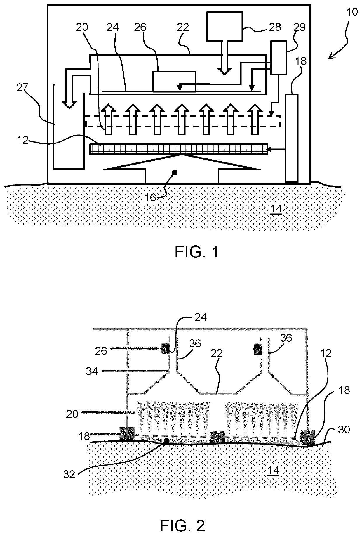
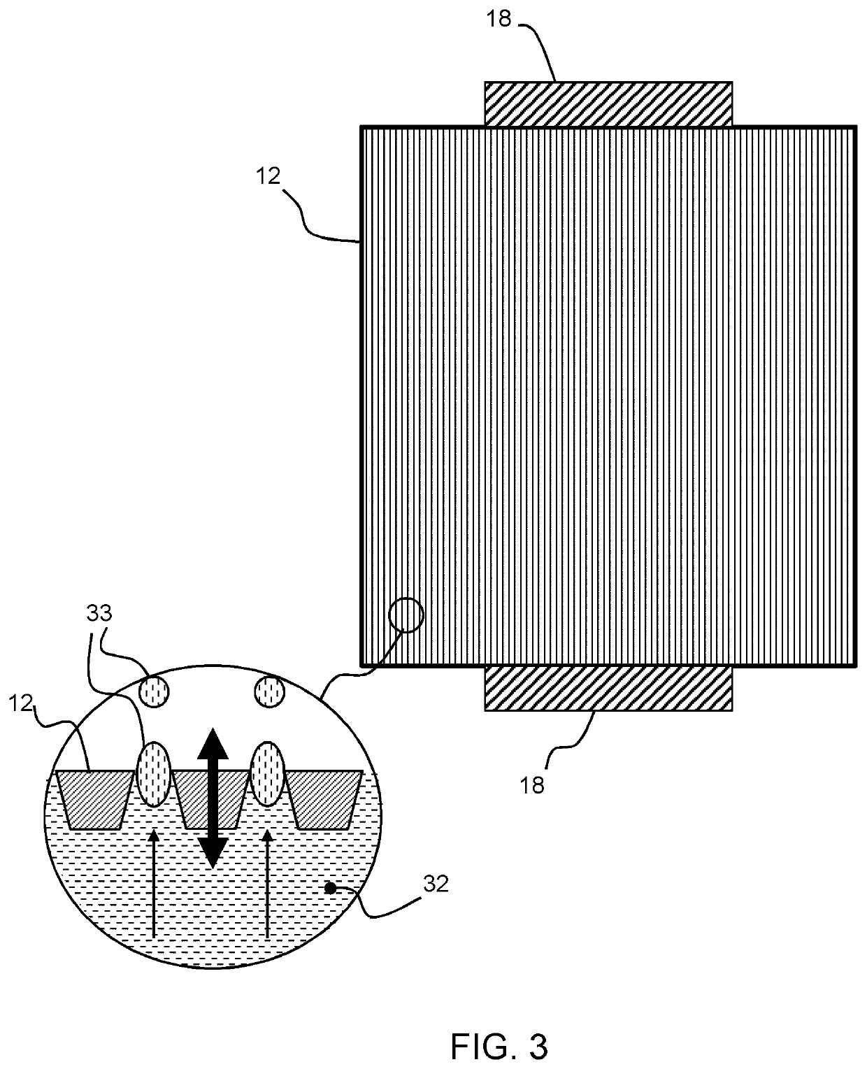
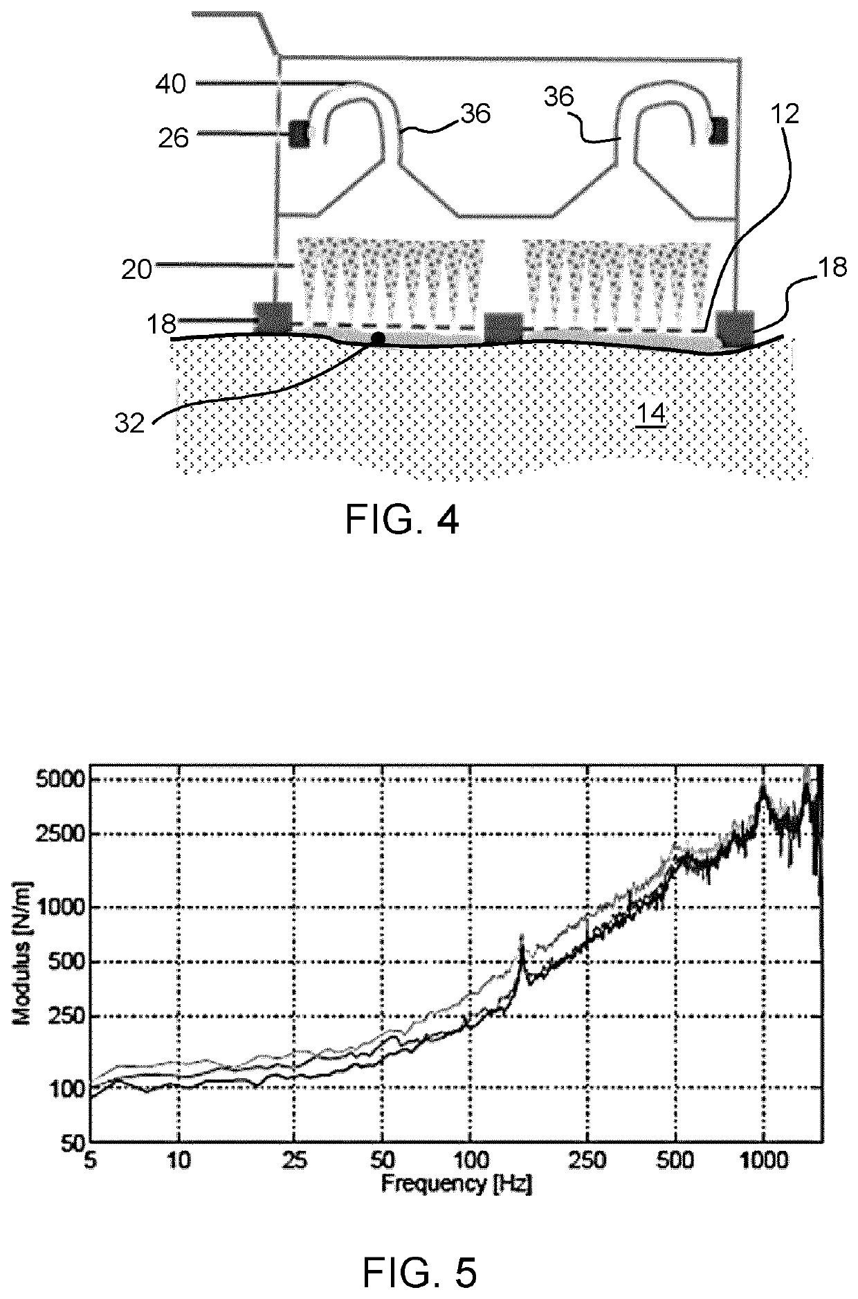
The patent describes a system that can monitor small amounts of sweat by using a chemical process called nebulization, which breaks down sweat from a surface to a sensing surface. The system can collect the sensed sweat and analyze it, allowing for continuous monitoring of biomarkers without the need for physical exercise. It can also have a discharge chamber to collect excess sweat and a dilution reservoir to increase the sample size. The system can be used for a fast transport of nebulized sweat, enabling the detection of biomarkers in small amounts of sweat without significant delay.

Problems solved by technology

The development of reliable sweat sensing has, however, been hampered by several issues, in spite of clinical work showing promising results as early as the 1940s and 1950s.
To date the impactful application of sweat analysis has been limited mainly to cystic fibrosis diagnostics, and drug and alcohol abuse testing.
However, historical studies in this area have involved relatively crude sampling techniques, such as collecting large sweat volumes in bags or textiles.
Deficiencies in such techniques may have been a contributing factor to this apparent lack of correlation.
However, the focus of this study is on the development and the integration of the sensors themselves which, whilst evidently crucial, does not address issues relating to sweat sample collection.
It is, however, likely that the time-dependent response of the sensor does not directly reflect the actual level of biomarkers over time because of accumulation effects.
The sample collection and presentation to the published sensors may not be well-controlled so that continuous reliable sensing over a long period of time is difficult.
Such patches may also not be designed to handle the tiny amounts of sweat that are produced under normal conditions, i.e. in the order of nanoliters per minute per sweat gland.
There remain problems of biomarker sensing of very small volumes of sweat of the order of nL / min / gland.
The filling time of microfluidic devices is then long and there is a substantial time delay between the sweat excretion to the skin and actual measurement, which can be as much as several hours of delay.

Method used


Image

  • A sweat sensing system
  • A sweat sensing system
  • A sweat sensing system

Examples


Embodiment Construction

[0051]The invention will be described with reference to the Figures.

[0052]It should be understood that the detailed description and specific examples, while indicating exemplary embodiments of the apparatus, systems and methods, are intended for purposes of illustration only and are not intended to limit the scope of the invention. These and other features, aspects, and advantages of the apparatus, systems and methods of the present invention will become better understood from the following description, appended claims, and accompanying drawings. It should be understood that the Figures are merely schematic and are not drawn to scale. It should also be understood that the same reference numerals are used throughout the Figures to indicate the same or similar parts.

[0053]The invention provides a sweat sensing system comprises a mesh for location over a sweat surface on which sweat is formed or collected and a vibration system for vibrating the mesh to nebulize sweat droplets. The neb...


PUM


Abstract

A sweat sensing system comprises a mesh for location over a sweat surface on which sweat is formed or collected, and a vibration system for vibrating the mesh to nebulize sweat droplets. The nebulized sweat droplets are condensed on a sensing surface, and a sweat sensor performs biomarker sensing of the sweat at the sensing surface.

Description

FIELD OF THE INVENTION[0001]This invention relates to a sweat sensing system, for example for monitoring biomarkers in sweat.BACKGROUND OF THE INVENTION[0002]Non-invasive, semi-continuous and prolonged monitoring of biomarkers that indicate disease / health status and well-being is in demand for monitoring, for example, dehydration, stress, sleep, children's health and in perioperative monitoring.[0003]Sweat, tear fluid and saliva may all be obtained non-invasively. Sweat is a particularly accessible bio fluid, and is a rich source of information relating to the physiology and metabolism of a subject.[0004]Continuous monitoring of high-risk patients, such as those with serious chronic conditions, pre- or post-operative patients, and the elderly, using sweat biomarker monitoring devices can provide higher quality diagnostic information than regular biomarker spot checks as normally done by repeatedly drawing multiple blood samples. Such continuous monitoring may be in a hospital settin...

Claims


Application Information

Patent Timeline
Patent Type & Authority Applications(United States)
IPC IPC(8): A61B5/145A61B5/00
CPCA61B5/14517A61B5/6833A61B5/0051A61B5/4266A61B10/0064A61B2010/0009
Inventor DELLIMORE, KIRAN HAMILTON J.PELSSERS, EDUARD GERARD MARIEJOHNSON, MARK THOMASGERHARDT, LUTZ CHRISTIANVAN LIESHOUT, RON MARTINUS LAURENTIUS
Owner KONINKLJIJKE PHILIPS NV
Learn More