
Active implantable medical device having transparent encapsulation

a medical device and transparent technology, applied in the field of active implantable medical devices with transparent encapsulation, can solve the problems of low to no transmission to rf, visible and ir wavelengths, and inability to mri-friendly,

Active Publication Date: 2022-06-30
SYNERGIA MEDICAL
View PDF0 Cites 0 Cited by
  • Summary
  • Abstract
  • Description
  • Claims
  • Application Information

AI Technical Summary

Benefits of technology

The patent is about a method for filling the space inside an electronic device with a resin that may contain a filler to prevent shrinkage. This resin and filler are both transparent to the given wavelength range. Additionally, the patent describes a method for creating walls with a varying thickness to reduce the space between the electronic circuitry and the walls. The exposed surface of the device is defined by a protective polymeric layer or a cover, and any uncovered surfaces have a minimum radius of curvature to prevent damage to nearby tissue. Overall, the patent aims to provide a safer, reliable, and effective method for protecting and insulating electronic devices during implantation.

Problems solved by technology

Encapsulations made of titanium have, however, low to no transmission to RF, visible and IR wavelengths, and are not MRI-friendly, generating heat and imaging artefacts.
Polymers have been tested for encapsulations, but they generally lack durability and resistance to moisture.
Because of the use of electric wires, in particular when coiled, such implants can be unsafe to use with magnetic resonance imaging (MRI) apparatuses and also with simple metal detecting portals as used in airports, banks, and the like.
The reduced dimensions of this housing substantially limit the functionalities and the medical applications thereof to monitoring of biomarkers.
For example, it is impossible to lodge a battery in such small volume.
These materials are very expensive and difficult to shape, thus reducing the available geometries to flat surfaces.
Furthermore, this housing is made of several components and of different materials, requiring multiple and sometimes delicate joining operations yielding many joint interfaces, which long term moisture tightness is difficult to ensure.
This, however, is only possible in very small dimensions, too small for housing the electronic required for any transfer of energy, or with a number of individual parts made of different materials and soldered together with a soldering metal.
This in turn increase production costs and is highly detrimental to the hermeticity of the housing, i.e., it cannot be fully air-; liquid-, and moisture-tight.

Method used


Image

  • Active implantable medical device having transparent encapsulation
  • Active implantable medical device having transparent encapsulation
  • Active implantable medical device having transparent encapsulation

Examples


Embodiment Construction

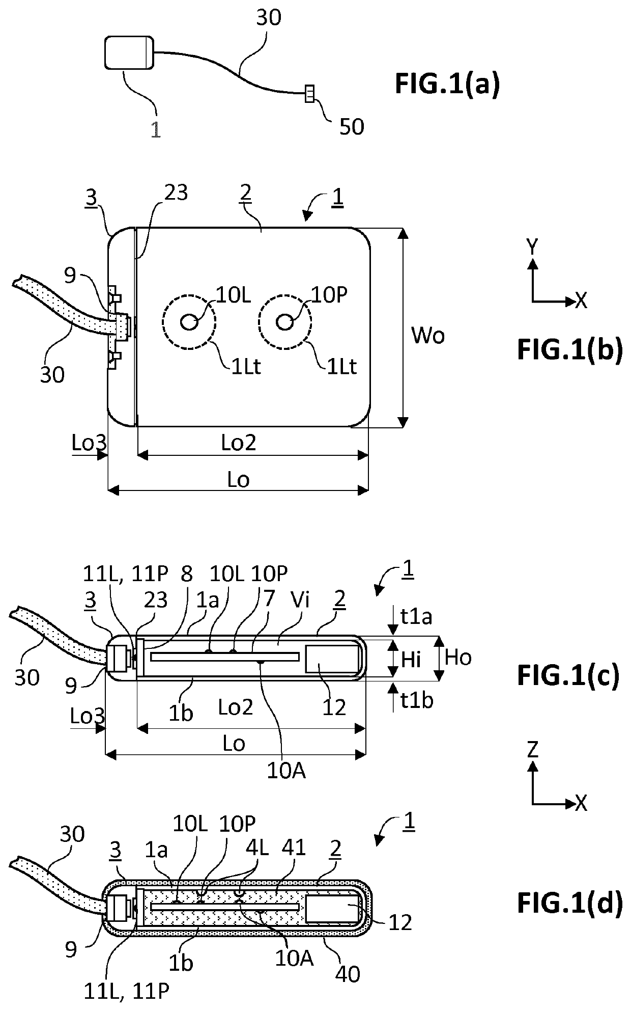
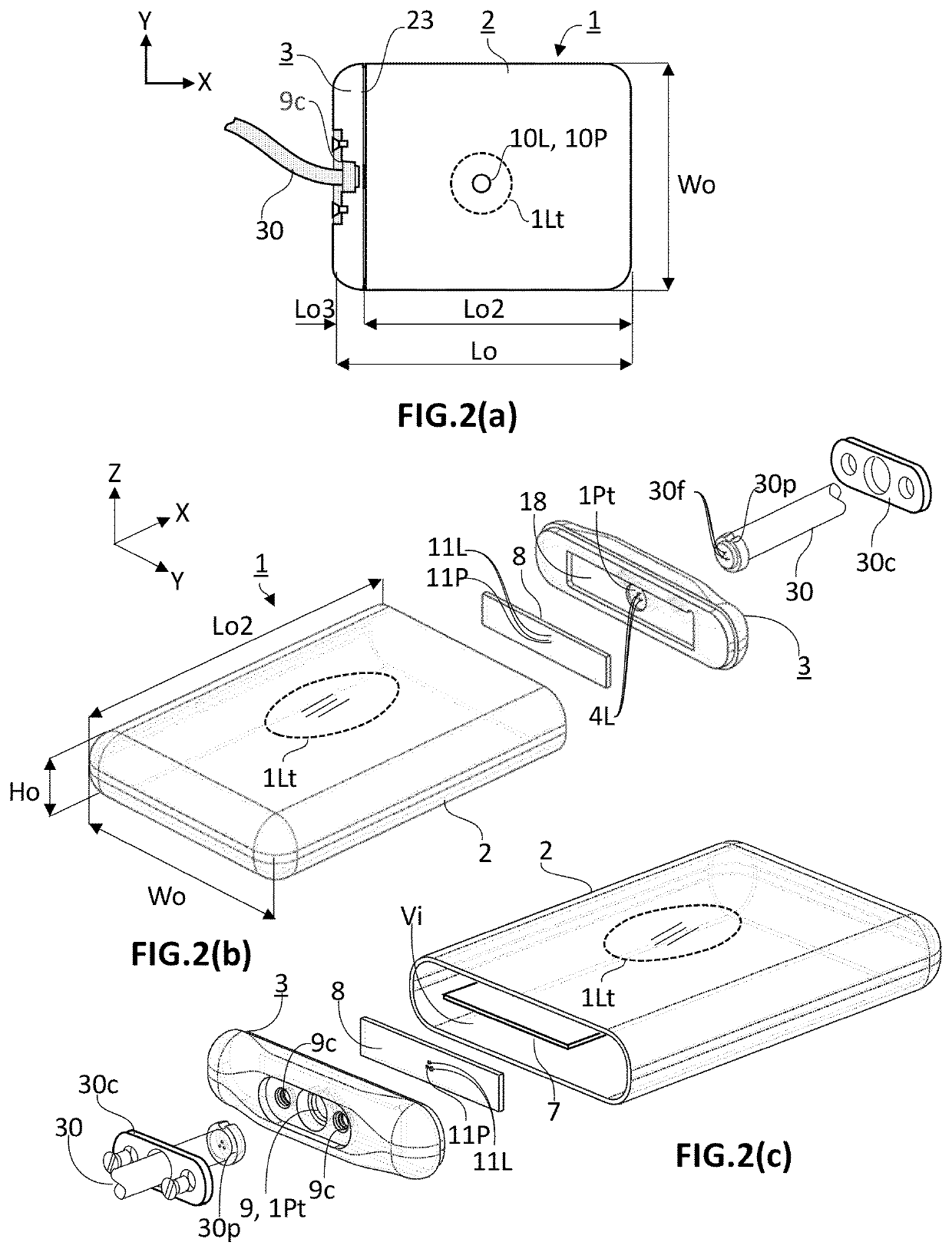
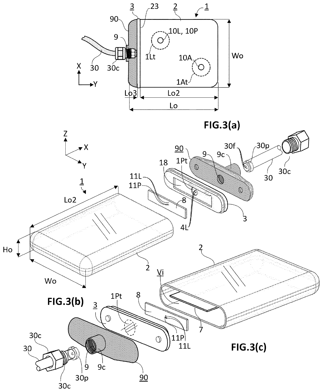
[0058]The present invention concerns an active implantable medical device (AIMD) for implantation in a body of a patient. The AIMD is capable of communicating with an exterior of the body it is implanted in by transmission of electromagnetic radiations of at least a given wavelength range comprised between 380 and 2200 nm (=visible and near-infrared ranges). The AIMD comprises a housing defining an inner space of volume (Vi) sealingly separated from an outer environment by walls defined by an inner surface defining the boundaries of the inner space and by an outer surface in contact with the outer environment. The outer surface is defined by a length (Lo) measured along a first axis (X), a width (Wo) measured along a second axis (Y), and a height (Ho) measured along a third axis (Z) with X ⊥ Y ⊥ Z.

[0059]The inner space encloses an electronic circuitry. The electronic circuitry includes a main source of light (10L) and / or a first photodetector (10P). The main source of light (10L) an...


PUM


Abstract

An active implantable medical device includes an encapsulation (1) defining an inner space sealingly separated from an outer environment by walls transparent to a given wavelength range.The walls have a first main wall (1a) and a second main wall (1b) facing one another and separated from one another by an inner height (Hi) of the inner space. An encapsulation includes a housing formed by a first component (2) and a second component (3) both made of a single material and hermetically joined to one another along a single interface (23) to define the inner space hermetically sealed by the walls from the outer environment.An inner space contains an electronic, and facing a wall of the encapsulation.wherein joining of the first component and second components (2, 3) is carried out by welding without addition of a third material, the inner space has a volume (Vi) of at least 2 cm3.

Description

TECHNICAL FIELD[0001]The present invention is in the field of active implantable medical devices (AIMD) for use in medical treatment of a patient. The AIMD of the present invention comprises an encapsulation configured for transmitting light through a skin of the patient or towards a target organ or vessel and / or for receiving optical signals either from outside the patient's body or reflected by the target organ or vessel. The AIMD of the present invention can advantageously further comprise a tissue coupling unit separate from the encapsulation and coupled thereto by means of a lead, for transfer of stimulating pulses between an implantable pulse generator (IPG) enclosed in the encapsulation and the tissue coupling unit and for stimulation of a biological tissue which the tissue coupling unit is coupled to. It is particularly advantageous for an IPG producing optical energy transferred through an optical fibre to a photovoltaic cell comprised in the tissue coupling unit for conver...

Claims


Application Information

Patent Timeline
Patent Type & Authority Applications(United States)
IPC IPC(8): A61N5/06A61N1/372A61N1/375A61N1/378A61N1/05
CPCA61N5/0622A61N1/37217A61N1/375A61N1/3787A61N2005/0662A61N1/0551A61N2005/0626A61N2005/066A61N2005/0661A61N5/0601A61N2005/0659
Inventor GODFRAIND, CARMENDOGUET, PASCALDE COCK DE RAMEYEN, AURÉLIENIEUWENHUYS, AURORE
Owner SYNERGIA MEDICAL
Learn More