Coiling device for a large range of metal strip thicknesses

a technology of coiling device and metal strip, which is applied in the direction of web handling, thin material handling, transportation and packaging, etc., can solve the problem that it is not possible in the prior art to use the same coiling device to coil strips, and achieve the effect of rapid, precise and robust manner, and favorable deflection of forces

Pending Publication Date: 2022-06-23
PRIMETALS TECH AUSTRIA GMBH
View PDF34 Cites 0 Cited by
  • Summary
  • Abstract
  • Description
  • Claims
  • Application Information

AI Technical Summary

Benefits of technology

[0032]This configuration has the effect that, in the extended position of the flap extension, for the purpose of guiding a thin metal strip, guidance over a relatively large section (namely the length of the upper duct flap plus the length of the flap extension) is achieved and, in the retracted position of the flap extension, the required freedom of movement for displacing the upper duct flap between the position in which it covers the front pressure roller and the position in which it frees up the front pressure roller is available.
[0033]Preferably, at its end furthest away from the coiler, the flap extension is mounted in an articulated manner such that the transfer of the flap extension from the retracted position to the extended position and back...

Problems solved by technology

Conversely, it is not possible in the prior art to use the same coiling de...

Method used


Image

  • Coiling device for a large range of metal strip thicknesses
  • Coiling device for a large range of metal strip thicknesses
  • Coiling device for a large range of metal strip thicknesses

Examples


Embodiment Construction

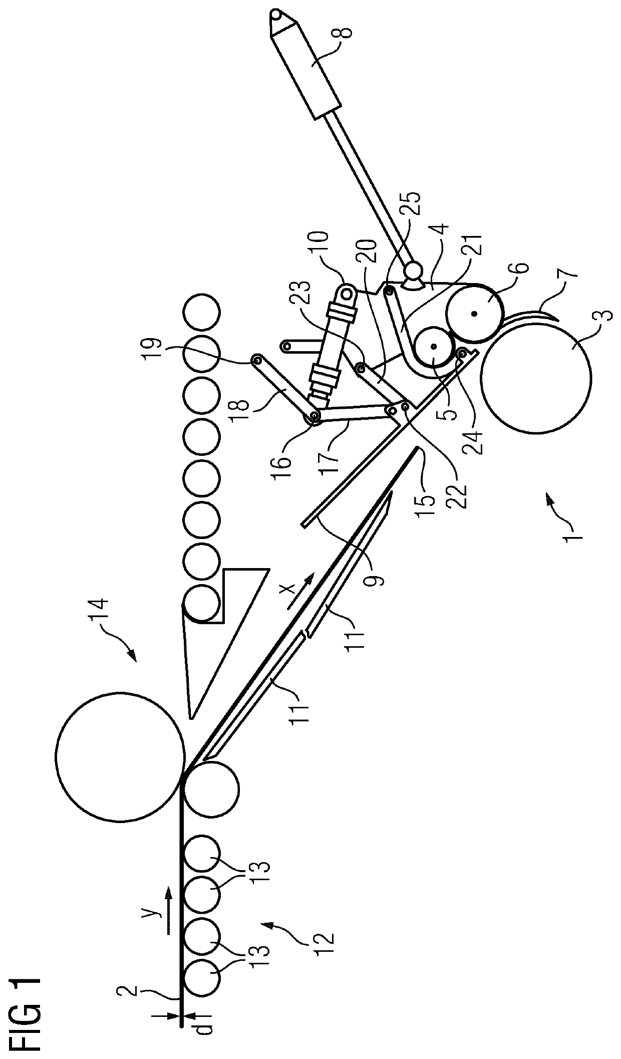
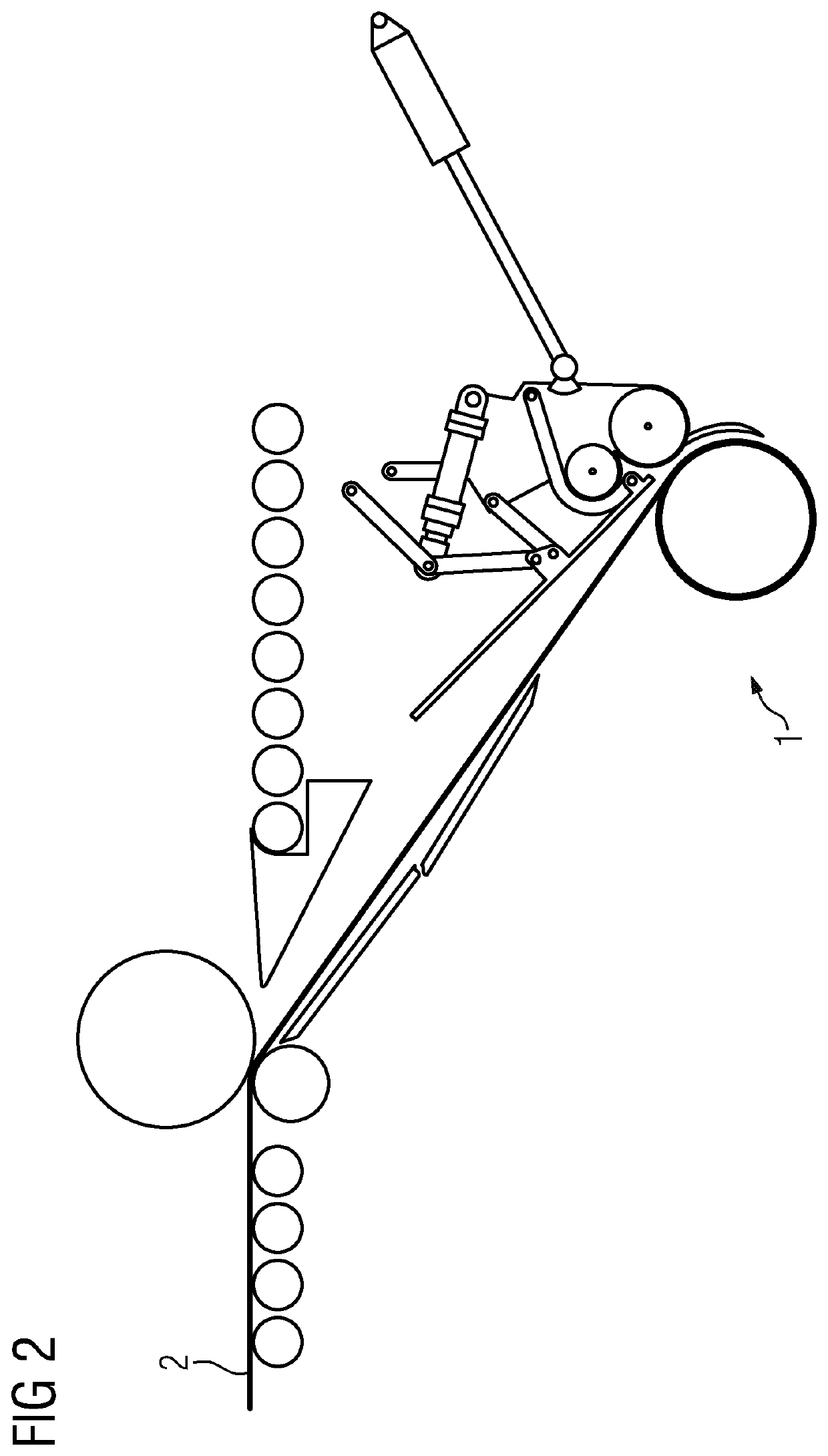
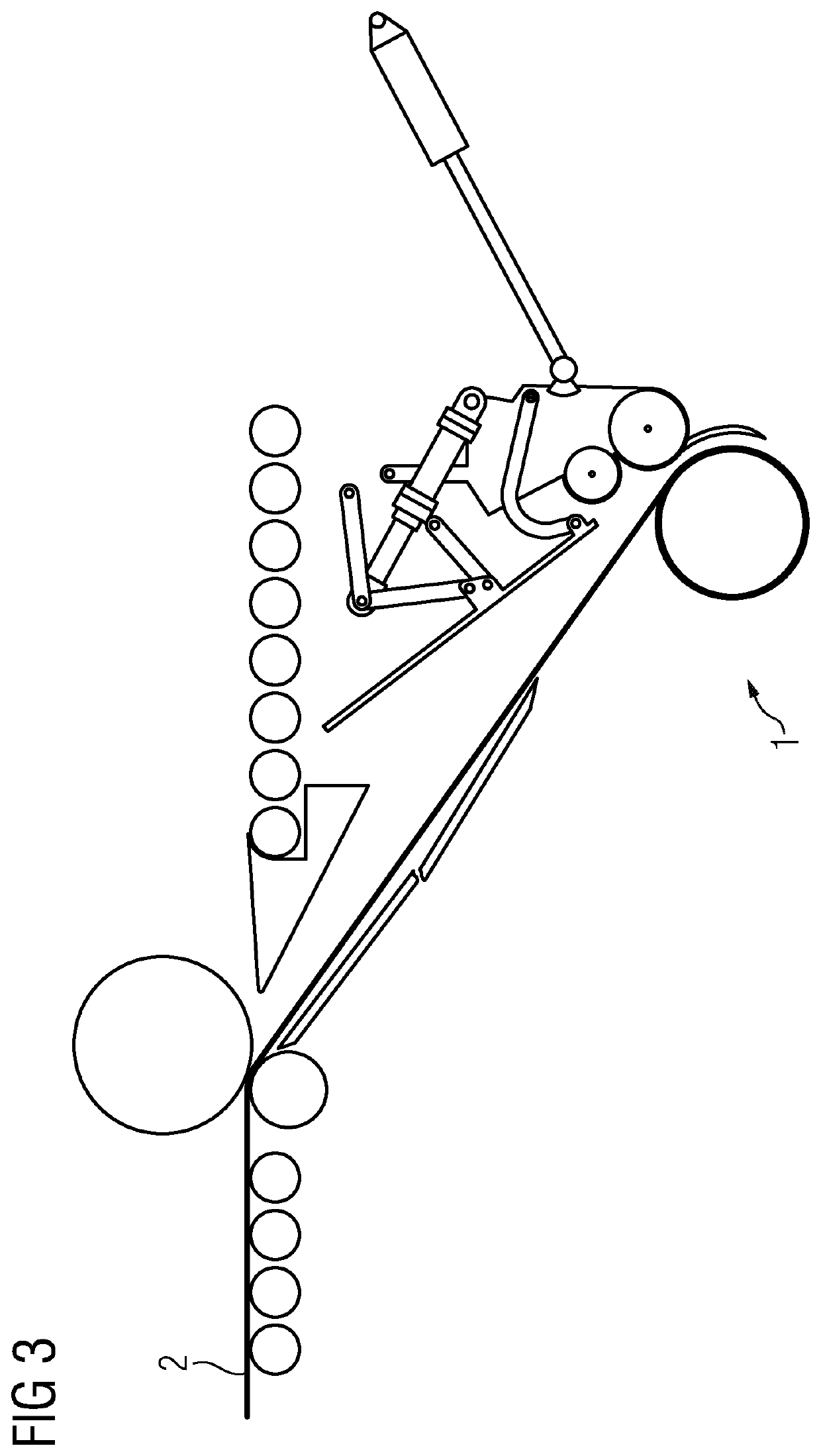
[0043]FIGS. 1 to 5 show the same coiling device. The elements illustrated in FIGS. 1 to 5 are also the same. For this reason, only FIG. 1 allows all of the reference designations. Only a few reference designations that are required for understanding and elucidation are illustrated in FIGS. 2 to 5.

[0044]In FIGS. 1 to 5, a coiling device comprises a coiler 1. A metal strip 2 is fed in a feed direction x to the coiler 1 wherein the strip is intended to be coiled by the coiler 1. The metal strip 1 may be composed, for example, of steel or aluminum. The coiler 1 has a coiling mandrel 3 operable for coiling the metal strip 2. The coiling mandrel 3 may be expandable. This is generally customary and is therefore not discussed in more detail below. The rest of the construction of the coiler 1 is also conventional and is therefore not discussed in more detail.

[0045]The coiling device further comprises a coiling swing arm 4. The coiling swing arm 4 has, for its part, a front pressure roller 5,...


PUM

PropertyMeasurementUnit
Thicknessaaaaaaaaaa

Abstract

A coiling device includes a coiler (1) having a coiling mandrel (3) for coiling a metal strip (2) which is fed (x) to the coiler (1), and a coiling swing arm (4) having a front and a rear pressure roller (5, 6) and a deflection plate (7). A swing arm drive (8) lines up the coiling swing arm (4) with the coiling mandrel (3) and is driven away from the coiling mandrel (3). An upper duct flap (9) upstream of the coiler (1) in the feed direction (x) for guiding the metal strip (2). A flap drive (10) for positioning the upper duct flap (9) such that, when the coiling swing arm (4) is lined up with the coiling mandrel (3), the upper duct flap is arranged between the coiling mandrel (3) and the front pressure roller (5) of the coiling swing arm (4) or is arranged upstream of the front pressure roller (5) of the coiling swing arm (4). In the first-mentioned case, the metal strip (2) is deflected around the coiling mandrel (3) only by the rear pressure roller (6) and the deflection plate (7) of the coiling swing arm (4) and, in the last-mentioned case, additionally also by the front pressure roller (5).

Description

CROSS-REFERENCE TO RELATED APPLICATIONS[0001]The present application which claims priority of European Patent Application No. 20216982.7 filed Dec. 23, 2020, the contents of which are incorporated by reference herein.TECHNICAL FIELD[0002]The present invention is based on a coiling device, wherein the coiling device comprises[0003]a coiler having a coiling mandrel for coiling a metal strip which is fed in a feed direction to the coiler,[0004]a coiling swing arm having a rear pressure roller and a deflection plate,[0005]a swing arm drive by means of which the coiling swing arm can be lined up with the coiling mandrel and driven away from the coiling mandrel, and[0006]an upper duct flap which is arranged upstream of the coiler as seen in the feed direction for the purpose of guiding the metal strip to the coiler.[0007]The present invention furthermore relates to an operating method for a coiling device for coiling a metal strip,[0008]wherein the metal strip is fed in a feed direction t...

Claims


Application Information

Patent Timeline
IPC IPC(8): B21C47/04
CPCB21C47/04B21C47/06B21C47/3433B21C47/3441B65H19/28B65H2301/41427B65H18/26B65H18/08B21C47/34B65H20/02B65H2701/173B21C47/02B65H18/10B21C47/063
Inventor BISCHOFF, MATTHIASHOFER, ROLANDNEUMÜLLER, MATHIASOSTHEIMER, PASCALSALZMANN, CHRISTOPHSCHWINGHAMMER, JAN
Owner PRIMETALS TECH AUSTRIA GMBH
Why Eureka
Try Eureka