Method and apparatus of full-field vibration measurement via microwave sensing

Pending Publication Date: 2022-06-16
SHANGHAI JIAO TONG UNIV
View PDF0 Cites 0 Cited by
  • Summary
  • Abstract
  • Description
  • Claims
  • Application Information

AI Technical Summary

Benefits of technology

The present invention provides a full-field vibration measurement method using multiple transmitting antennas to create a virtual antenna array, which increases the number of receiving antennas and baseband signal output channels. This allows for the accurate measurement of vibration information in the full field by positioning and resolving targets and measurement points based on a joint range-angle dimension and tracking phase evolution. The invention can effectively suppress interference, improve measurement precision, and enhance anti-interference capability and reliability. The method also has a very high calculation efficiency.

Problems solved by technology

In terms of multi-measurement point vibration measurement, scanning is required, and the laser Doppler vibration measurement technology cannot achieve multi-measurement point synchronous vibration measurement and is limited in scanning scope.
For the vision-based vibration measurement technology, it is used to extract vibration information by means of visual image processing, but it is generally low in measurement precision, large in amount of calculation and narrow in vibration amplitude and frequency response scope, and is easily affected by light and the like.
However, due to the lack of a range sensing capability, the former can only be used for the vibration measurement of a single target or a single measurement point, but not to resolve multiple targets or multiple measurement points, and is easily interfered by other clutters in the radiation scope of a radar beam.
A significant challenge of the vibration measurement based on microwave sensing is clutter interference, including interference of clutters reflected by static targets in the radiation scope of a radar beam, coupling interference of signals reflected by adjacent targets, aliasing interference of signals from targets in the same range cell, etc.
Because the vibration measurement based on a frequency modulated continuous wave radar makes it possible to resolve different targets and / or measurement points by range, it is limited by a transmission bandwidth, and often has a limited range resolution and serious problems of static clutter interference, adjacent multi-component coupling interference, and aliasing interference of components in the same range cell.
Moreover, when multiple interferences are coupled together in practical applications, it is difficult in the prior art to achieve effective interference suppression and compensation, and high-precision deformation and vibration measurement cannot be achieved.
However, for full-field vibration measurement, the targets and / or measurement points are distributed in a plane and in space, causing the problems of difficulty in resolving the targets and / or measurement points in adjacent range cells and inability of resolving the targets and / or measurement points in the same range cell, etc., making it difficult to extract and measure synchronous vibration information of the targets and / or measurement points within the full field.

Method used


Image

  • Method and apparatus of full-field vibration measurement via microwave sensing
  • Method and apparatus of full-field vibration measurement via microwave sensing
  • Method and apparatus of full-field vibration measurement via microwave sensing

Examples


Embodiment Construction

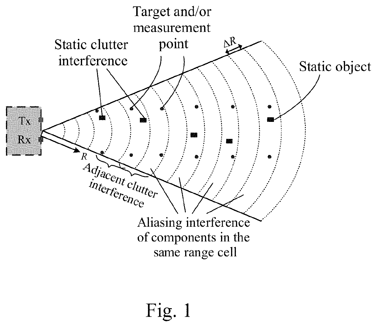
[0046]As shown in FIG. 1, in the prior art, measurement targets and / or measurement points are positioned in different range cells by beat frequency information of intermediate frequency baseband signals, and then interference phase evolution of each measurement point is tracked and estimated, so as to extract vibration information of the targets and / or measurement points. However, due to the limitation of a transmission bandwidth, the range resolution is limited, and static clutter interference, mutual interference of components in adjacent range cells, aliasing interference of components in the same range cell, and coupling interference of a plurality of interference sources make it impossible to realize accurate vibration information measurement of multiple targets and / or measurement points in the prior art, but are often used for vibration measurement of targets and / or measurement points distributed along a line and spaced farther apart. In addition, as shown in FIG. 1, two targe...


PUM


Abstract

The present invention relates to a full-field vibration measurement method based on microwave sensing, which is characterized by comprising the following steps: step 1, repeatedly transmitting linear frequency modulated continuous wave microwave signals by means of one or more transmitting antennas; step 2, receiving reflected signals from targets and / or measurement points by means of a plurality of receiving antennas, and performing frequency mixing on received signals and local oscillator signals to obtain multi-channel intermediate frequency baseband signals; step 3, acquiring intermediate frequency baseband signals in various channels, and resolving and positioning targets and / or measurement points within the full field based on a joint range and angle dimension; and step 4, extracting vibration displacement time-domain information of targets to be measured and / or measurement points. By means of the full-field vibration measurement method based on microwave sensing provided in the present invention, synchronous vibration information measurement of targets and / or measurement points within the full field is achieved by positioning and resolving the targets and / or measurement points within the full field based on a joint range-angle dimension and tracking phase evolution, thereby solving the difficulties in the prior art that full-field vibration measurement and interference suppression cannot be achieved.

Description

FIELD OF THE INVENTION[0001]The present invention relates to the technical field of non-contact vibration measurement, and in particular to a full-field vibration measurement method and system based on microwave sensing.DESCRIPTION OF THE PRIOR ART[0002]Vibration measurement is an important way to achieve the test of mechanical properties of structures, health monitoring and fault diagnosis, and the extraction of other micro-motion features. Non-contact vibration measurement has obvious advantages in terms of easiness to mount sensors, measurement of lightweight and large-scale structures, etc. Currently, common non-contact vibration measurement technologies comprise a laser Doppler vibration measurement technology and a vision-based vibration measurement technology. For the laser Doppler vibration measurement technology, it is used to measure the vibration velocity based on a laser Doppler frequency shift caused by vibration, and it often can only test at a single point and has hig...

Claims


Application Information

Patent Timeline
IPC IPC(8): G01M7/02G01S13/88G01S13/82G01S7/35
CPCG01M7/025G01S7/35G01S13/82G01S13/88G01M7/00G01H9/002G01S13/34G01S13/42
Inventor PENG, ZHIKEXIONG, YUYONGMENG, GUANG
Owner SHANGHAI JIAO TONG UNIV
Why Eureka
Try Eureka