Magnetic latch for fastening a hinged closure member to a support

a technology of hinged closure and magnetic latch, which is applied in the direction of building locks, construction fastening devices, construction, etc., can solve the problems of difficult and cumbersome lifting of the actuator

Pending Publication Date: 2022-06-09
LOCINOX NV
View PDF17 Cites 3 Cited by
  • Summary
  • Abstract
  • Description
  • Claims
  • Application Information

AI Technical Summary

Benefits of technology

The patent text describes a latch bolt assembly used in a closure member. The assembly includes a stronger magnetic attraction between the latch bolt and the keeper assembly, which allows the latch bolt to be pulled from a greater distance with greater force. This distance between the two parts can exceed 10 mm, and the increased magnetic attraction ensures that the latch bolt remains in place even if the closure member moves or sags. The latch bolt assembly also includes a biasing member that pushes the latch bolt into its retracted position to ensure a reliable closing of the closure member even in cases where it may not close quickly.

Problems solved by technology

This force reduction is beneficial since, otherwise, the increased magnetic attraction would make it very difficult and cumbersome to lift the actuator.

Method used


Image

  • Magnetic latch for fastening a hinged closure member to a support
  • Magnetic latch for fastening a hinged closure member to a support
  • Magnetic latch for fastening a hinged closure member to a support

Examples


first embodiment

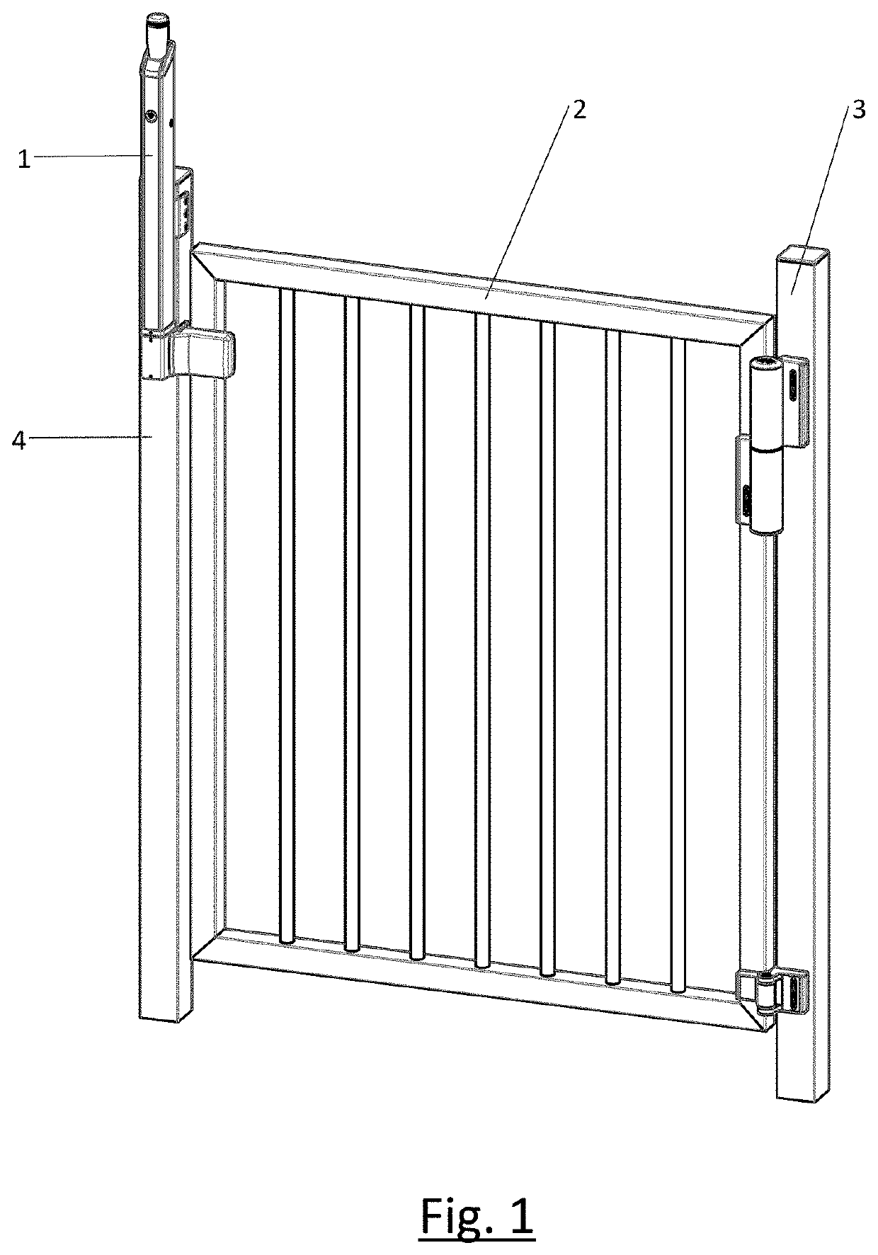
[0147]FIG. 1 shows a perspective view of a magnetic latch assembly 1 mounted on a closure system. The closure system comprises a closure member 2 that is hinged on a first support 3 and that may be fastened to a second support 4 by means of the magnetic latch assembly 1. In the illustrated embodiment, the closure member 2 is formed by a gate and the supports 3, 4 are formed by fixed posts, but it will be readily appreciated that the magnetic latch assembly 1 is also suitable for other kinds of closure members (e.g. a sliding closure member, a door, etc.) and / or supports. For example, the support may be formed by a closure member in case the magnetic latch assembly 1 is used on a double gate.

[0148]The magnetic latch assembly 1 generally comprises a latch bolt assembly 5 and a magnetic keeper assembly 6 as shown in FIG. 2. In the illustrated embodiment, the latch bolt assembly 5 is mounted on the support 4 and the magnetic keeper assembly 6 is mounted on the closure member 2, but it w...

second embodiment

[0170]a magnetic latch assembly 1′ will be described with reference to FIGS. 11A to 18. Elements in the magnetic latch assembly 1′ will be indicated with the same reference numbers as corresponding elements in the magnetic latch assembly 1. The magnetic latch assembly 1′ is mounted on a closure system. The closure system comprises a closure member 2 that is hinged on a first support 3 and that may be fastened to a second support 4 by means of the magnetic latch assembly 1. In the illustrated embodiment, the closure member 2 is formed by a gate and the supports 3, 4 are formed by fixed 1′, but it will be readily appreciated that the magnetic latch assembly 1′ is also suitable for other kinds of closure members (e.g. a sliding closure member, a door, etc.) and / or supports. For example, the support may be formed by a closure member in case the magnetic latch assembly 1′ is used on a double gate.

[0171]The magnetic latch assembly 1′ generally comprises a latch bolt assembly 5 and a magne...


PUM


Abstract

A magnetic latch for fastening a closure member to a support. The magnetic latch comprises a latch bolt assembly comprising: a first elongated housing configured to be mounted with its rear side facing either the closure member or the support; a second housing connected to and positioned underneath the first housing, the second housing being rotatable with respect to the first housing around the vertical direction between a first rotational position in which the latch bolt assembly is operable for a right-handed closure member and a second rotational position in which the latch bolt assembly is operable for a left-handed closure member; and a latch bolt mounted in the second housing. The different rotational positions of the second housing allow using a horizontally moveable latch bolt while retaining a symmetrical placement on the closure system irrespective of the handedness of the closure member.

Description

TECHNICAL FIELD[0001]The present invention relates to a magnetic latch for fastening a hinged closure member to a support.BACKGROUND ART[0002]A magnetic latch assembly comprises a latch bolt assembly configured to be mounted to one of the hinged closure member and the support and a magnet keeper assembly configured to be mounted to the other one of the hinged closure member and the support. The magnetic latch assembly can be mounted on various types of closure members, in particular a door or a gate. In several countries there are legal regulations for swimming pool gates. Most of these regulations specify a minimum height for the safety gates, a minimum height at which the actuator for opening the closure member are to be located, and / or required minimal and / or maximal force required to actuate the actuator. A common way to meet these requirements is by mounting the latch bolt assembly in an upright position on top of the gate with the actuator on the upper side of the latch bolt a...

Claims


Application Information

Patent Timeline
Patent Type & Authority Applications(United States)
IPC IPC(8): E05C19/16E05C1/00E05C1/16
CPCE05C19/163E05C1/166E05C1/006E05C19/168E05B63/04E05B65/0007
Inventor TALPE, JOSEPH
Owner LOCINOX NV
Why Eureka
Try Eureka