Road Surface Matting

a technology for road surfaces and paving, applied in the field of matting, can solve problems such as wear and tear, and achieve the effect of avoiding wear and tear

Pending Publication Date: 2022-05-26
ANSON ANTHONY
View PDF0 Cites 0 Cited by
  • Summary
  • Abstract
  • Description
  • Claims
  • Application Information

AI Technical Summary

Problems solved by technology

The manner in which the Banting mat is constructed places inordinate reliance on the fabric, which makes it vulnerable to wear and tear.

Method used


Image

  • Road Surface Matting
  • Road Surface Matting
  • Road Surface Matting

Examples


Embodiment Construction

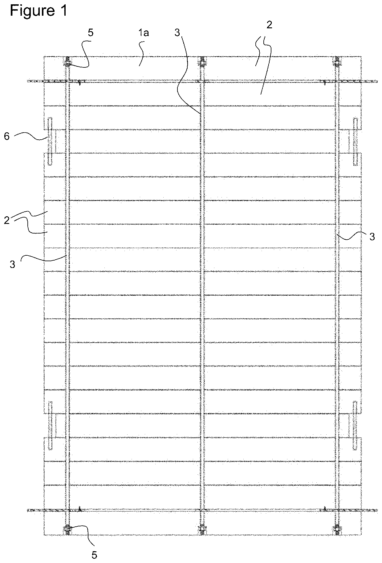
[0027]Referring to FIG. 1, the mat la has a series of beams 2 arranged in parallel. In this example the beams 2 are glued in sets of two or four, and are connected and tensioned by a series of spine rods 3 running perpendicular to and through the beams 2. As shown, the ends of each spine rod 3 are recessed in the end beams and are held there by lock nuts 5. Handles 6 are set into side recesses to provide grips for carrying the mat if need be.

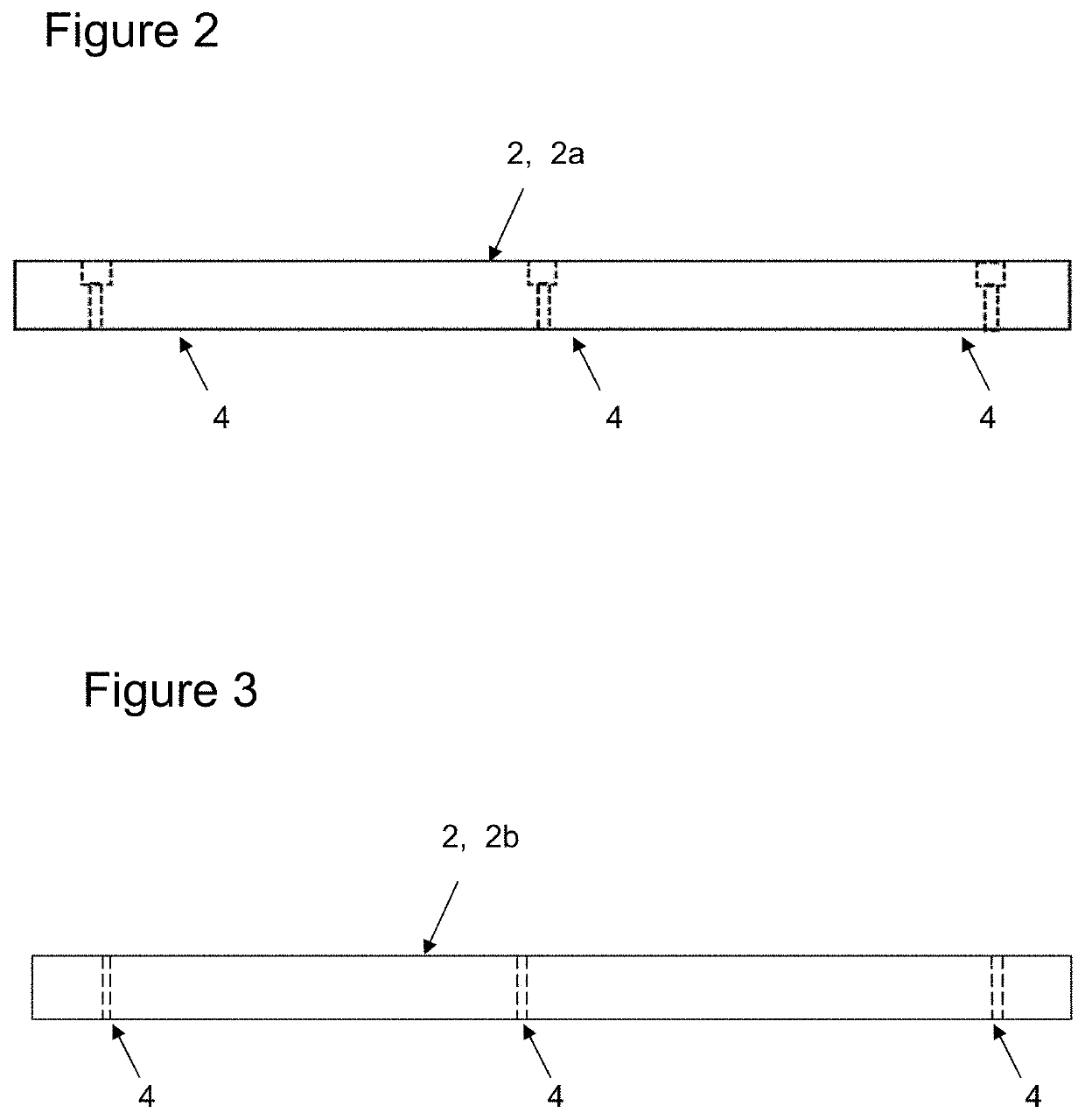
[0028]FIG. 2 illustrates detail one of the beams 2a at the end of the mat, and FIG. 3 illustrates detail of one of the beams 2b in a central part of the mat. The beams are such that the spine rods 3 pass through the holes 4 indicated by dotted lines.

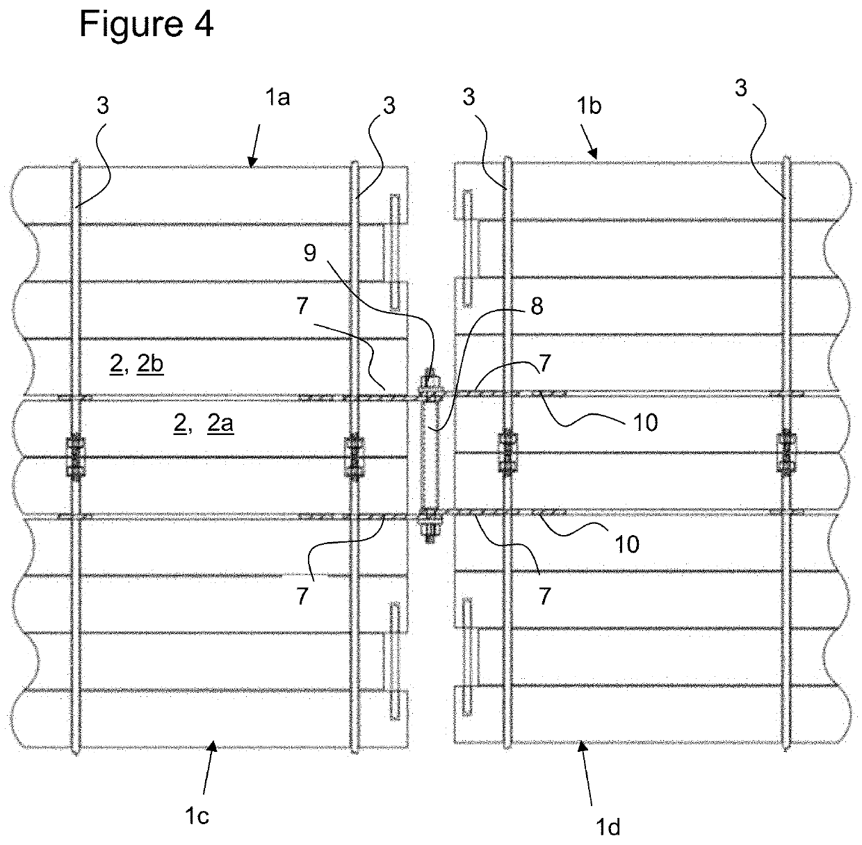
[0029]FIG. 4 illustrates how four of the mats 1a-d are joined ‘side to side’ and ‘end to end’. As shown, the spine rods 3 at adjacent corners of the mats 1a, 1b are joined to one another by way of locking plates 7 and a central connecting rod 8 with bolts 9 at each end. The spine rods 3 at adjacent c...


PUM

PropertyMeasurementUnit
compression densityaaaaaaaaaa
thickaaaaaaaaaa
thickaaaaaaaaaa

Abstract

A problem with unpaved roads is that they can be prone to damage when driven on. The road surface matting includes a first mat 1a and a second mat 1b, each mat having a series of substantially parallel beams 2, a plurality of spine rods 3 that run substantially perpendicular to and through the beams and connect the beams to one another. Each mat also has a joiner 7 adjacent an edge of the mat, arranged so that one of the spine rods passes through the joiner. The matting is such that the first and second mats are connected to one another by way of a connecting rod 8 that passes through and joiner 8 of one mat and the joiner 8 of the other mat.

Description

FIELD OF THE INVENTION[0001]This invention relates to matting for use in providing a road surface.BACKGROUND[0002]It is known to overlay the ground with mats to make a better surface for vehicles to drive on, for example in unpaved areas where vehicles would otherwise have to travel over an inadequate ground surface. US patent specification No. 2006 / 0222804 by Banting discloses a road matting where, among other things, a series of beams are arranged in parallel, each within its own pocket in a fabric mat. The manner in which the Banting mat is constructed places inordinate reliance on the fabric, which makes it vulnerable to wear and tear. It is an object of the present invention to go at least some way towards providing a useful alternative.DEFINITIONS[0003]The terms “comprising” or “having”, if and when used in relation to one or more features, in each case indicates minimum features present but does not rule out the option of there being further features that are not mentioned. T...

Claims


Application Information

Patent Timeline
Patent Type & Authority Applications(United States)
IPC IPC(8): E01C5/00E01C5/14E01C9/08
CPCE01C5/005E01C2201/165E01C9/086E01C5/14E04F2201/0594E01C2201/16
Inventor ANSON, ANTHONY
Owner ANSON ANTHONY
Why Eureka
Try Eureka