
Modular electrical power subsystem architecture

a subsystem and modular technology, applied in the field of spacecraft, can solve the problems of limited ability to reject, system modularity, and inability to adapt to different payload components, and achieve the effect of increasing the current discharge ra

Pending Publication Date: 2022-05-19
RAYTHEON CO
View PDF12 Cites 0 Cited by
  • Summary
  • Abstract
  • Description
  • Claims
  • Application Information

AI Technical Summary

Benefits of technology

The patent describes an electrical power system for a spacecraft that includes two batteries with varying discharge rates. One battery is designed to accept and supply a certain amount of current to operate the spacecraft's payload, while the other battery is designed to meet the payload's higher current needs. This dual battery configuration allows for modularity of the system and also enables the battery charge management unit to be decoupled from the spacecraft's bus for parallel testing and integration. The technical effect of this system is that it provides flexibility to meet varying mission operational demands while ensuring the battery charges and discharges according to the payload's needs.

Problems solved by technology

For example, the bus of the spacecraft may not anticipate intermittent operation of high powered payloads and may provide power choices and thermal technologies that do not support high discharge currents.
Additionally, conventional subsystems may also be deficient in being adaptable with different payload components.
The battery is connected directly to the solar array of the spacecraft bus, such that the system is not modular.
Still other deficiencies of the known subsystem may include mission constraints driven by limits on the ability to reject the heat generated by the power subsystem and the inability to source the short-term electrical power to provide increased payload operation as required during a mission.

Method used


Image

  • Modular electrical power subsystem architecture
  • Modular electrical power subsystem architecture
  • Modular electrical power subsystem architecture

Examples


Embodiment Construction

[0042]The principles described herein have application in a spacecraft or spacecraft for aerospace deployment, generally outside of the atmosphere of a planet. The disclosure is more particularly directed to a small spacecraft, such as a spacecraft having a mass of 500 kilograms (1,100 pounds) or less. The principles described herein may be suitable for spacecrafts of any size. The spacecraft may be launched in an Earth orbit, such as in a low Earth orbit, by any suitable launch vehicle. In other exemplary applications, the principles described may be suitable for operation in any orbit, such as a high Earth orbit, geosynchronous Earth orbit, or even Deep Space. Any suitable payload may be carried by the spacecraft.

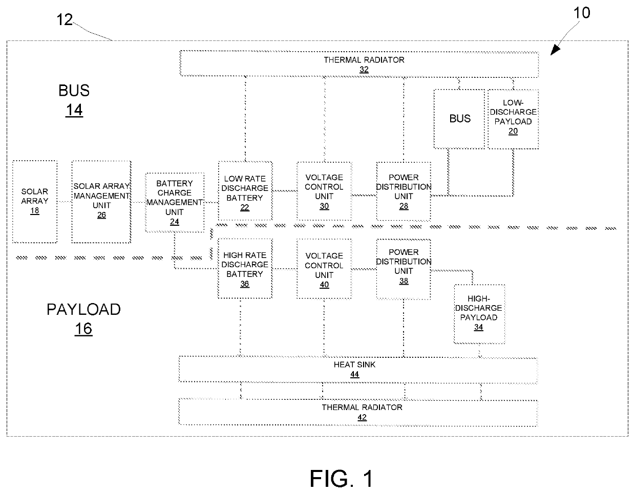
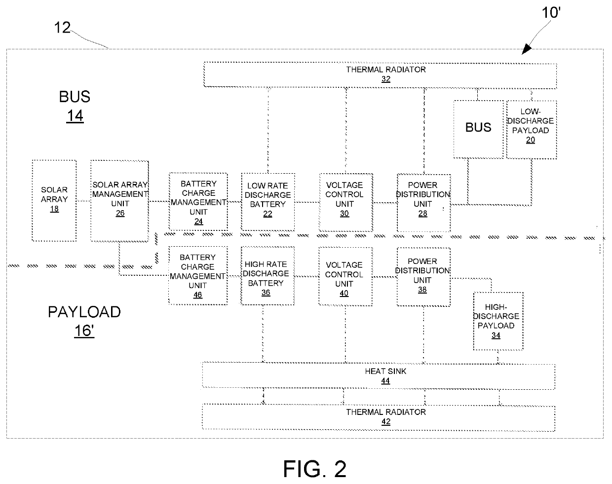
[0043]Referring first to FIG. 1, an electrical power system 10 for a spacecraft 12 is shown. The electrical power system 10 is configured to provide electrical power generation, storage, and distribution for the spacecraft 12. The electrical power system 10 includes a bus...


PUM


Abstract

An electrical power system has a dual battery configuration that enables sufficient power supply for a spacecraft bus and a payload module being carried by the spacecraft. During a sunlight power mode, power is drawn from a solar array of the bus to power a low-discharge payload of the spacecraft and a high-discharge payload of a payload module. During the sunlight power mode, a low rate discharge battery and a high rate discharge battery are charged by a battery charge management unit of the spacecraft bus. During an eclipse power mode, the low rate discharge battery powers the low-discharge payload of the spacecraft and the high rate discharge battery powers the high-discharge payload of the payload module. The high-rate discharge battery may also be used to power the high-rate discharge payload in the sunlight power mode to meet its high current demands to meet a flexible mission operations.

Description

FIELD OF DISCLOSURE[0001]The disclosure relates to spacecraft and more particularly, to an electrical power system or subsystem for spacecraft.DESCRIPTION OF THE RELATED ART[0002]Spacecraft may be configured to carry payloads, such as communication antennas, receivers, transmitters, etc. Small spacecraft use electrical power subsystems that may be undersized for use with some payloads, such as payloads that have a high peak power, a short duty-cycle, and are configured to have mission utility at any time and at any location in an orbit. For example, the bus of the spacecraft may not anticipate intermittent operation of high powered payloads and may provide power choices and thermal technologies that do not support high discharge currents. Additionally, conventional subsystems may also be deficient in being adaptable with different payload components.[0003]One prior attempt to provide an electrical power subsystem for a spacecraft includes using a self-contained battery without space...

Claims


Application Information

Patent Timeline
IPC IPC(8): H02J7/35H02J7/00B64G1/42B64G1/44B64G1/58H01M10/42H02S50/00H02S40/38
CPCH02J7/35H02J7/0024H02J7/0014H02J7/0063H02J7/007B64G1/428H01M2010/4271B64G1/443B64G1/58H01M10/425H02S50/00H02S40/38B64G1/425B64G1/44B64G1/50B64G1/503H02J2310/44H02J7/0068Y02E10/50Y02E60/10Y02E70/30
Inventor COSNER, CHRISTOPHER M.STICKELMAIER, JOHN F.WOOTAN, JOHN J.
Owner RAYTHEON CO
Learn More