
Refrigerator

a technology of refrigerator and cooling chamber, which is applied in the field of refrigerators, can solve the problems of destroying cells, affecting the taste of food, and affecting the operation of the machine, so as to reduce the flow resistance, smoothly supply the cool air, and reduce the amount of the discharged cold air as it moves

Pending Publication Date: 2022-05-12
LG ELECTRONICS INC
View PDF0 Cites 0 Cited by
  • Summary
  • Abstract
  • Description
  • Claims
  • Application Information

AI Technical Summary

Benefits of technology

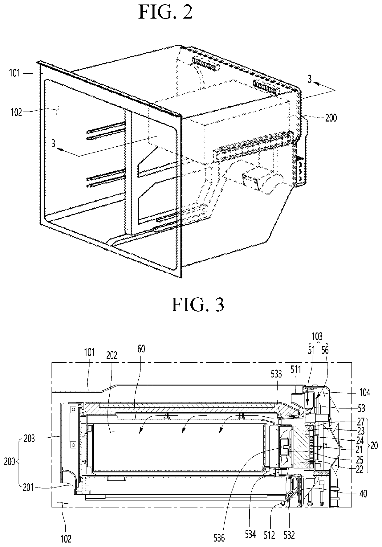
The refrigerator in this patent has several benefits. First, a suction type cooling fan reduces resistance when compared to a blower type fan, which means it can handle larger amounts of food without getting stuck. Second, a guide duct smoothly supplies cool air forward from the rear side of the deep freezing compartment, ensuring the cold air reaches the front without resistance. Third, regardless of the amount of food stored in the deep freezing compartment, the cold air is uniformly distributed throughout the whole area. Fourth, a gradual increase in the area of the cold air discharge hole in the guide duct ensures the amount of cold air is balanced between the front and intermediate points of the deep freezing compartment. This reduces the decrease in the amount of cold air as it moves away from the cooling fan.

Problems solved by technology

However, when food such as meat or seafood is stored in the frozen state in the existing freezing compartment, moisture in cells of the meat or seafood are escaped out of the cells in the process of freezing the food at the temperature of −20° C., and thus, the cells are destroyed, and taste of the food is changed during an unfreezing process.
In the case of such a cold air circulation structure, when a lot of food is loaded at a rear side of the drawer, or a box-shaped object is stored at the rear side of the drawer, there is a problem in that circulation of cold air in the deep freezing compartment is not smoothly performed due to flow resistance.
Thus, there is a problem in that a load of the cooling fan excessively increases, and power consumption increases.
Above all, temperature distribution in the deep freezing compartment is not uniformly maintained, and a temperature at a rear side of the deep freezing compartment may be very low, but a temperature at a front side of the deep freezing compartment may be high.

Method used


Image

  • Refrigerator
  • Refrigerator
  • Refrigerator

Examples


Embodiment Construction

[0033]Hereinafter, a refrigerator according to an embodiment of the present invention will be described in detail with reference to the accompanying drawings.

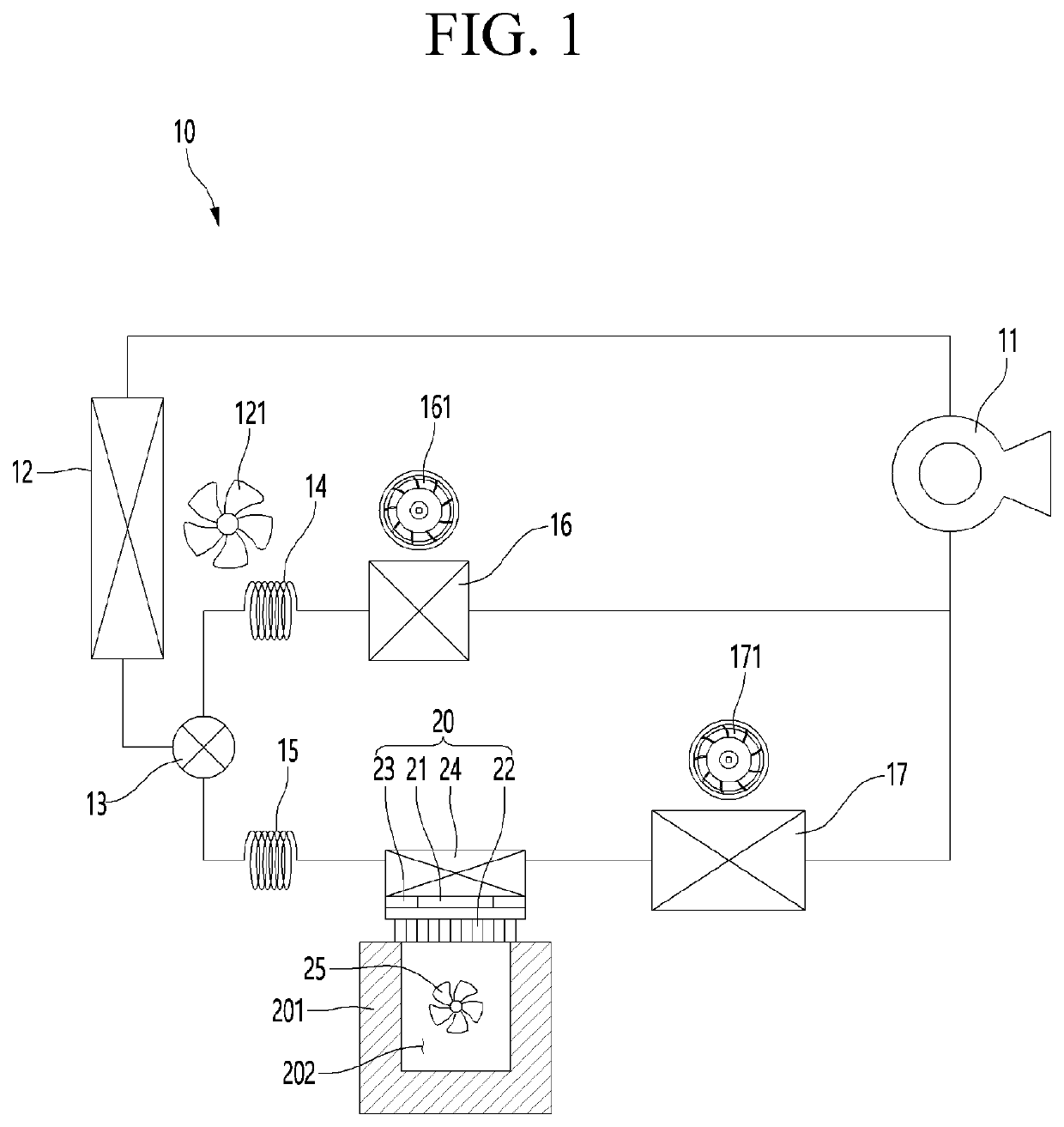
[0034]FIG. 1 is a view illustrating a refrigerant circulation system of a refrigerator according to an embodiment of the present invention.

[0035]Referring to FIG. 1, a refrigerant circulation system according to an embodiment of the present invention includes a compressor 11 that compresses a refrigerant into a high-temperature and high-pressure gaseous refrigerant, a condenser 12 that condenses the refrigerant discharged from the compressor 11 into a high-temperature and high-pressure liquid refrigerant, an expansion valve that expands the refrigerant discharged from the condenser 12 into a low-temperature and low-pressure two-phase refrigerant, and an evaporator that evaporates the refrigerant passing through the expansion valve into a low-temperature and low-pressure gaseous refrigerant. The refrigerant discharged from the e...


PUM

PropertyMeasurementUnit
temperatureaaaaaaaaaa

Abstract

In addition, the thermoelectric element may be a cascade type thermoelectric element in which two thermoelectric elements having the same or different specifications are coupled to each other.

Description

TECHNICAL FIELD[0001]The present invention relates to a refrigerator.BACKGROUND ART[0002]In general, a refrigerator is a home appliance for storing food at a low temperature, and includes a refrigerating compartment for storing food in a refrigerated state in a range of 3° C. and a freezing compartment for storing food in a frozen state in a range of −20° C.[0003]However, when food such as meat or seafood is stored in the frozen state in the existing freezing compartment, moisture in cells of the meat or seafood are escaped out of the cells in the process of freezing the food at the temperature of −20° C., and thus, the cells are destroyed, and taste of the food is changed during an unfreezing process.[0004]However, destruction of cells may be minimized by setting a temperature condition of the storage compartment to a cryogenic state that is significantly lower than a temperature of the current freezing compartment so that food quickly passes through a freezing point temperature ra...

Claims


Application Information

Patent Timeline
Patent Type & Authority Applications(United States)
IPC IPC(8): F25B21/04F25D13/04F25D23/06
CPCF25B21/04F25D23/069F25D13/04F25B21/02F25D16/00F25D11/022F25B2321/023F25D17/062F25D11/025F25D2317/063F25D2317/0665F25D2317/0671
Inventor LIM, HYOUNGKEUNYUN, SEOKJUNSONG, SEONGMINLEE, JUNGHUNLEE, HOYOUN
Owner LG ELECTRONICS INC
Learn More