
Systems and method for an electric motor with pin-fin cooling

Pending Publication Date: 2022-05-05
DANA BELGIUM
View PDF11 Cites 0 Cited by
  • Summary
  • Abstract
  • Description
  • Claims
  • Application Information

AI Technical Summary

Benefits of technology

The invention is an electric motor with a cooling system. The motor has a casing and stator with pin-fins that extend out from the stator. These pin-fins create clearances to allow a coolant to flow between the casing and stator and cool the motor. This design increases the flow rate of the coolant and reduces thermal resistance, which helps to remove heat from the motor. This also reduces the likelihood of degradation of the coolant pump and increases the overall efficiency of the electric motor.

Problems solved by technology

However, the inventors herein have recognized potential issues with such systems.
As one example, components of the electric motor that come into direct contact with the coolant may slow a flow rate of coolant through the electric motor.
Components configured to be cooled by the coolant may be arranged directly in the flow path of the coolant, which may obstruct the flow of the coolant and reduce an amount of cooling of the electric motor by the coolant.
Further, the reduced flow rate of the coolant through the electric motor may increase a backpressure of a pump configured to flow the coolant to the electric motor and may increase a likelihood of degradation of the pump.

Method used


Image

  • Systems and method for an electric motor with pin-fin cooling
  • Systems and method for an electric motor with pin-fin cooling
  • Systems and method for an electric motor with pin-fin cooling

Examples


Embodiment Construction

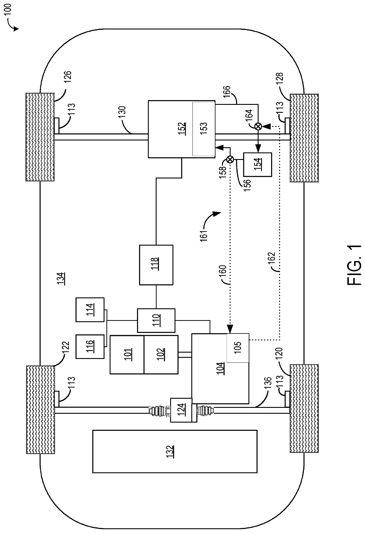
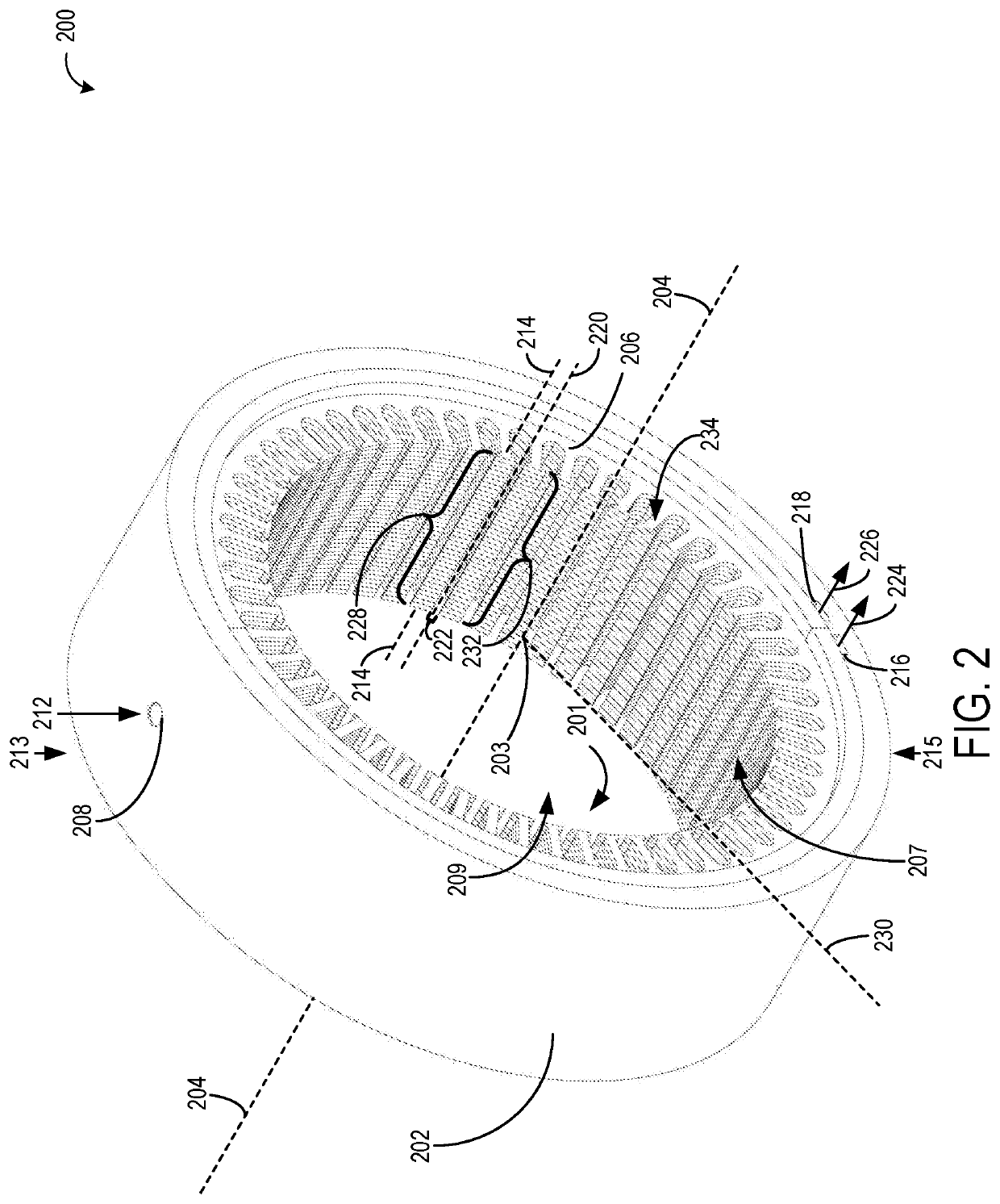
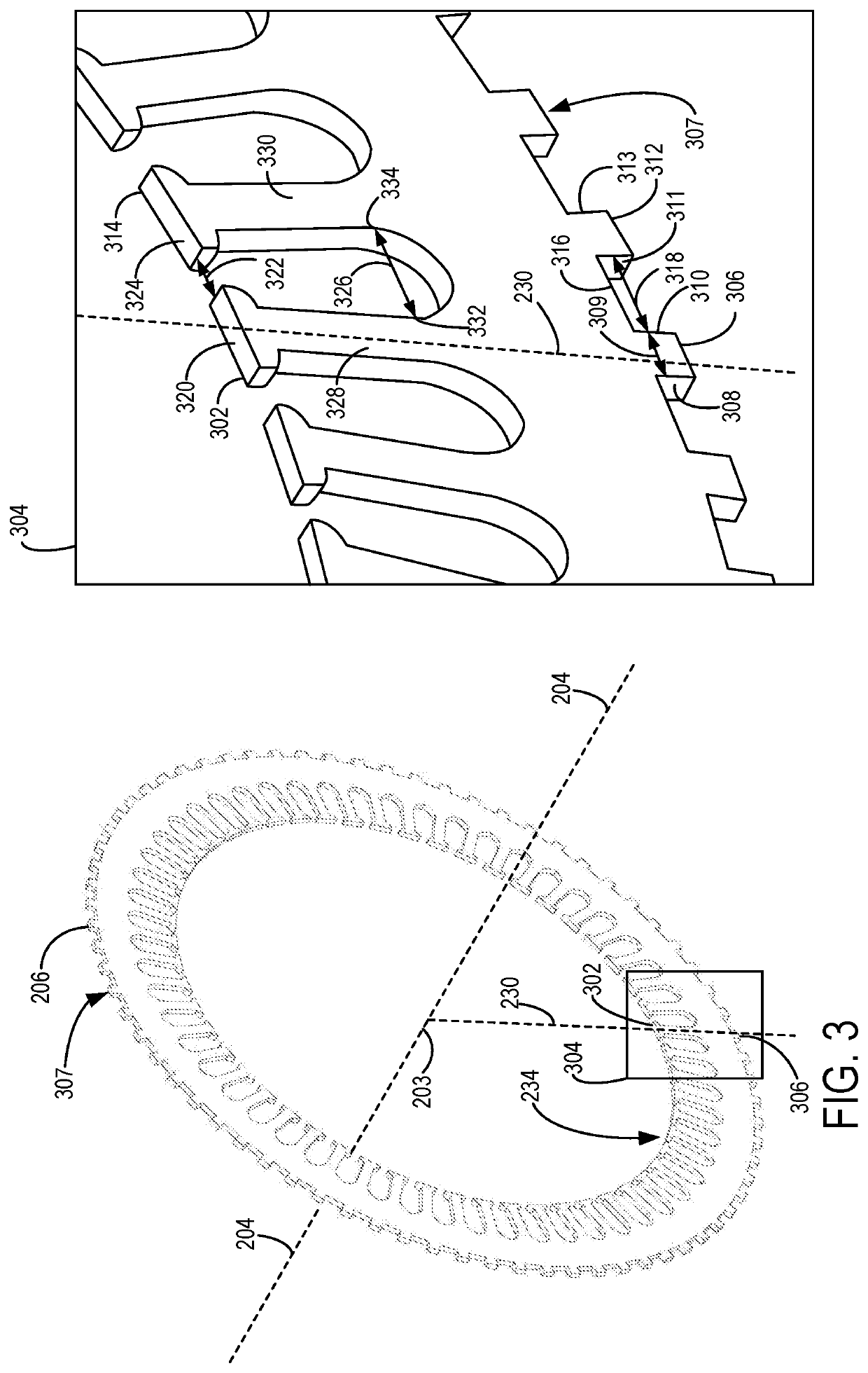
[0019]The following disclosure relates to methods and systems for thermal management of an electric motor of a vehicle. A vehicle, such as the vehicle shown by FIG. 1, includes an electric motor with a stator, such as the stator shown by FIG. 2. The stator may be housed inside a casing, where a coolant may circulate in a space between the stator and the casing to cool the electric motor. The stator may be a laminated stator, where the stator comprises a plurality of coaxially arranged annular plates, such as the annular plate shown by FIG. 3. Each angular plate may include an inner row of radially aligned teeth, and an outer row of radially aligned protrusions. The coaxially arranged annular plates may be configured such that the inner row of teeth of each annular plate are aligned, while the outer row of protrusions are misaligned (e.g., staggered), as shown by FIG. 4. An arrangement of pin-fins that extend to the casing may be formed on an outer surface of the stator by the protru...


PUM


Abstract

Various methods and systems are provided for thermal management of an electric motor via a coolant flow around portions of the electric motor, where the coolant flow is disrupted by an arrangement of pin-fins. In one example, an electric motor comprises: a casing including a coolant inlet arranged opposite to a coolant outlet across a central axis of the electric motor; a stator housed within the casing and forming a plurality of pin-fins extending straight outward radially, relative to the central axis, from outer circumferential surfaces of the stator in a staggered arrangement around an entire perimeter of the stator; and a plurality of clearances formed between adjacent pin-fins of the plurality of pin-fins, the plurality of clearances adapted to flow a coolant from the coolant inlet to the coolant outlet.

Description

TECHNICAL FIELD[0001]The present description relates generally to systems and methods for an electric motor, and more specifically, to thermal management of an electric motor.BACKGROUND AND SUMMARY[0002]For automotive applications, achieving a high level of performance and reliability of an electric motor may depend on thermal management, whereby heat generated during operation of the electric motor is transferred away from the electric motor. Some electric motors are configured to be cooled via a coolant, such as oil. The coolant may flow to one or more components of the electric motor and may remove heat from the electric motor.[0003]However, the inventors herein have recognized potential issues with such systems. As one example, components of the electric motor that come into direct contact with the coolant may slow a flow rate of coolant through the electric motor. Components configured to be cooled by the coolant may be arranged directly in the flow path of the coolant, which m...

Claims


Application Information

Patent Timeline
IPC IPC(8): H02K9/19H02K5/22B60K1/00B60L58/26
CPCH02K9/19H02K5/22H02K1/12B60L58/26B60K1/00H02K5/203H02K1/20B60L2240/545Y02T10/64Y02T10/70B60K2001/001
Inventor PAWAR, JAYWANT S.PRASHANT, CHETANTHAKARE, AMOL G.VANHEE, STEVEN
Owner DANA BELGIUM
Learn More