
Electric machines with features for enhancing load transfer performance of stacked-laminate rotors

a technology of stacked-laminate rotors and electric machines, which is applied in the direction of stator/rotor bodies, magnetic circuit rotating parts, magnetic circuit shape/form/construction, etc., can solve the problems of reducing the torque producing performance of the motor, reducing the salinity, and increasing the stress on the material, so as to enhance the load transfer performance and enhance the load transfer

Active Publication Date: 2022-04-28
GM GLOBAL TECH OPERATIONS LLC
View PDF24 Cites 2 Cited by
  • Summary
  • Abstract
  • Description
  • Claims
  • Application Information

AI Technical Summary

Benefits of technology

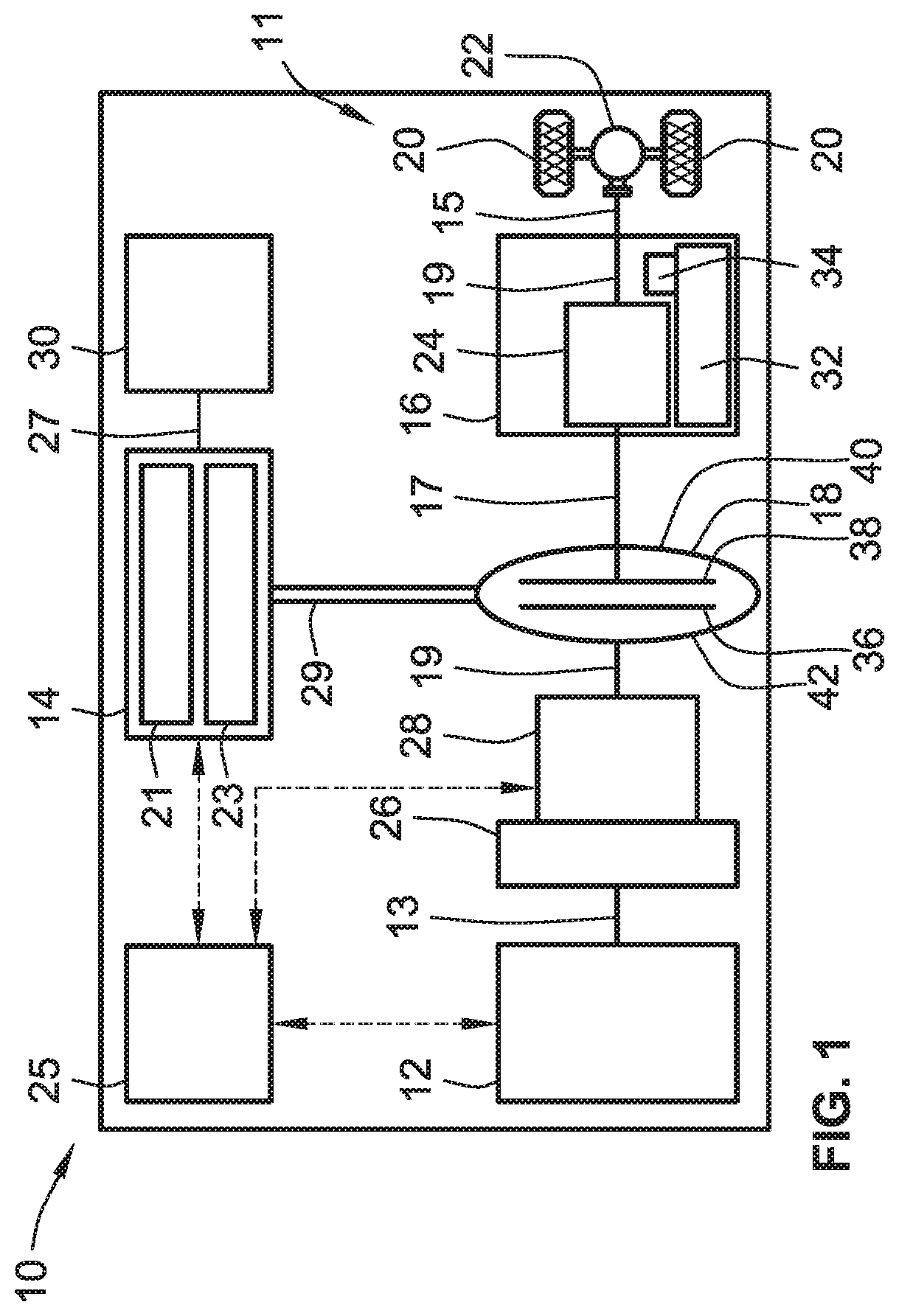
The patent text describes a new type of electric motor that is used in electric vehicles. These motors use a special design with multiple layers of magnets and conductive metal plates that work together to create a strong and efficient motor. The design also includes features that help transfer the load of the motor to the outer edges of the motor, which improves its performance. The technical effects of this design include increased efficiency, torque, and power output of the electric motor, as well as reduced magnetic flux leakage and improved load transfer between the motor's layers.

Problems solved by technology

When the rotor spins at high speeds, however, elevated levels of material stress may form in rotor material bridges between the magnetic rotor barriers and the empty cavities.
A simple solution to this mechanical stress problem would be to make the rotor bridges thicker; doing so, however, may diminish the torque producing performance of the motor by reducing magnetic flux as the thicker bridges “short circuit” the magnets residing in adjacent cavities, and by degrading the saliency characteristics of the rotor.

Method used


Image

  • Electric machines with features for enhancing load transfer performance of stacked-laminate rotors
  • Electric machines with features for enhancing load transfer performance of stacked-laminate rotors
  • Electric machines with features for enhancing load transfer performance of stacked-laminate rotors

Examples


Embodiment Construction

[0024]This disclosure is susceptible of embodiment in many different forms. Representative examples of the disclosure are shown in the drawings and herein described in detail with the understanding that these embodiments are provided as an exemplification of the disclosed principles, not limitations of the broad aspects of the disclosure. To that end, elements and limitations that are described, for example, in the Abstract, Introduction, Summary, Description of the Drawings, and Detailed Description sections, but not explicitly set forth in the claims, should not be incorporated into the claims, singly or collectively, by implication, inference, or otherwise. Moreover, the drawings discussed herein may not be to scale and are provided purely for instructional purposes. Thus, the specific and relative dimensions shown in the Figures are not to be construed as limiting.

[0025]For purposes of the present detailed description, unless specifically disclaimed: the singular includes the pl...


PUM


Abstract

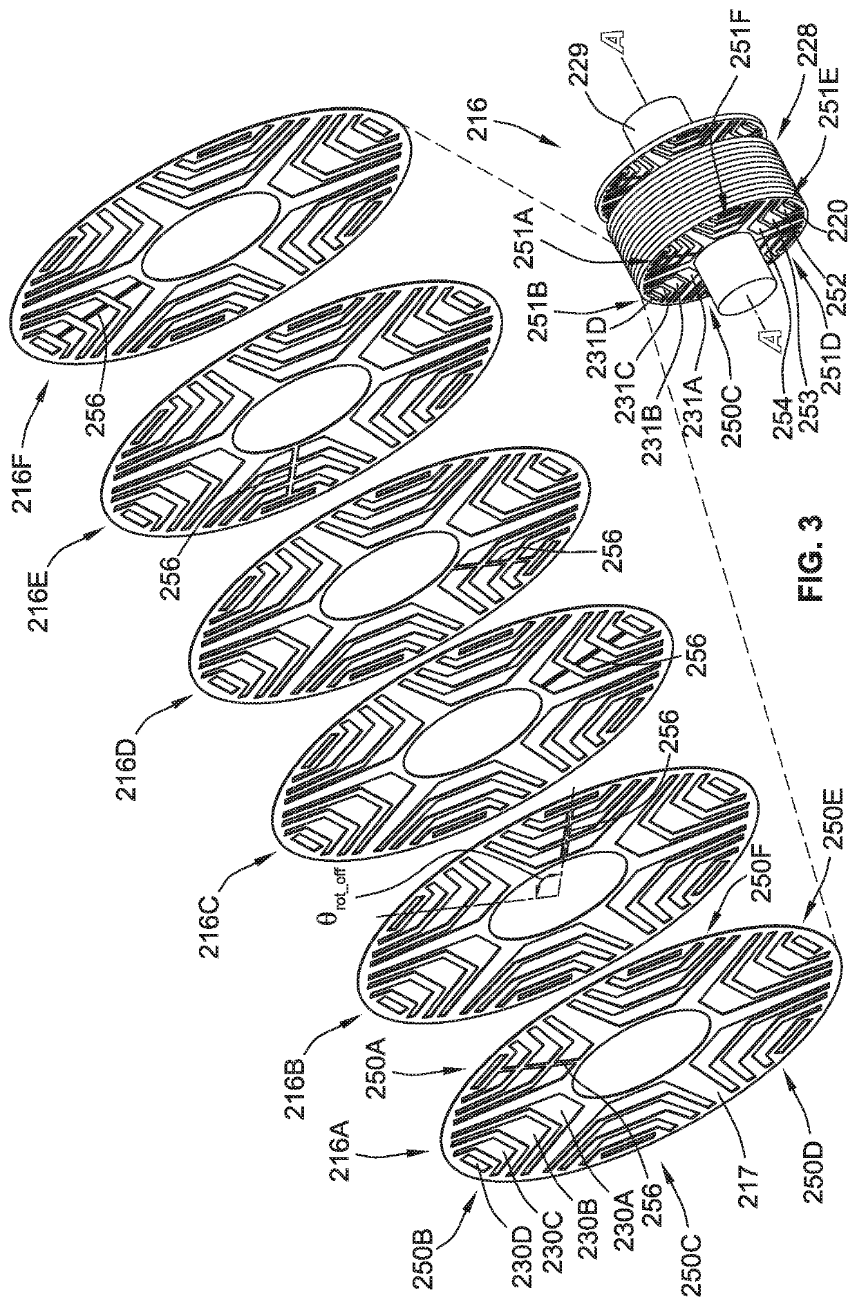
An electric machine includes a stator with stator slots securing therein electrically conductive windings. A rotor is rotatably mounted adjacent the stator and includes a stack of rotor laminates. Each laminate includes circumferentially spaced poles, each of which includes a magnet slot spaced from an insert slot. These laminate magnet slots cooperatively define the rotor's magnet slots. Likewise, the laminates' insert slots cooperatively define the rotor's insert slots. Magnets are mounted inside the rotor's magnet slots, and non-magnetic inserts are mounted inside the rotor's insert slots. One or more poles of each laminate includes a structural web that extends radially through the magnet and insert slots of that pole. Multiple poles of each rotor laminate lack a radially extending structural web. Each rotor laminate is rotated with respect to a neighboring rotor laminate such that each pole with a structural web axially aligns with a pole without a structural web.

Description

INTRODUCTION[0001]The present disclosure relates generally to electric machines. More specifically, aspects of this disclosure relate to multiphase, alternating current permanent magnet motor-generator units with stacked-laminate rotor assemblies reinforced with polymeric inserts.[0002]Current production motor vehicles, such as the modern-day automobile, are originally equipped with a powertrain that operates to propel the vehicle and power the vehicle's onboard electronics. In automotive applications, for example, the vehicle powertrain is generally typified by a prime mover that delivers driving torque through an automatic or manually shifted power transmission to the vehicle's final drive system (e.g., differential, axle shafts, road wheels, etc.). Automobiles have historically been powered by a reciprocating-piston type internal combustion engine assembly due to its ready availability and relatively inexpensive cost, light weight, and overall efficiency. Such engines include com...

Claims


Application Information

Patent Timeline
Patent Type & Authority Applications(United States)
IPC IPC(8): H02K1/27H02K15/03H02K21/14
CPCH02K1/276H02K21/14H02K15/03H02K1/274H02K1/28H02K1/246H02K1/165H02K3/04H02K3/28B60K6/26H02K2213/03H02K1/2766
Inventor COPPOLA, ANTHONY M.FATEMI, ALIREZALEONG, YEW SUMHOLMES, ALAN G.
Owner GM GLOBAL TECH OPERATIONS LLC
Learn More