
Purging system and use thereof in an energy system

Pending Publication Date: 2022-04-14
HPS HOME POWER SOLUTIONS GMBH
View PDF0 Cites 0 Cited by
  • Summary
  • Abstract
  • Description
  • Claims
  • Application Information

AI Technical Summary

Benefits of technology

The present invention aims to reduce the risk of explosions caused by hydrogen gas in a purging process. This is done through simple and cost-effective measures to modify the purging system. The technical effects of the invention include increased safety and reliability in the purging process.

Problems solved by technology

Such a rinse, also referred to as “purging”, is particularly necessary in order to lead away undesired foreign gas components, and liquid water which accumulates locally in the cell structures and which negatively influences the performance and the service life of the fuel cell device and / or of the electrolysis device, at regular intervals or depending on the operating modes.
However, a fan represents a further system component which requires energy and which causes additional costs and requires installation space.
The use of additional fans is therefore disadvantageous.
However, this would complicate the operation of the purging system and thus of the energy system.
However, this is too inaccurate.
In addition, large safety factors must be used.
Error triggering is also possible.
The use of a hydrogen sensor also does not provide any measure for reducing the hydrogen content in the discharge volume flow.
The use of a gas monitoring device is usually subject to a maintenance interval.

Method used


Image

  • Purging system and use thereof in an energy system
  • Purging system and use thereof in an energy system
  • Purging system and use thereof in an energy system

Examples


Embodiment Construction

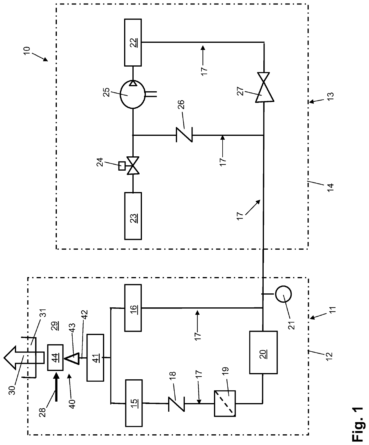
[0073]As can be seen from FIG. 1, the energy system 10 initially comprises a first subsystem 11, which is configured as an inner system. This means that the first subsystem 11 is located inside the house. The individual components of the first subsystem 11 are accommodated in a first system cabinet 12. In addition, the energy system 10 comprises a second subsystem 13 in the form of an outer system. This means that the second subsystem 13 is located outside the house. The second subsystem 13 also comprises a series of different components housed in a second system cabinet 14.

[0074]The first subsystem 11 comprises a first energy source device 15, which is an electrolysis device for producing hydrogen. In addition, the first subsystem 11 comprises a first energy sink device 16, which is a fuel cell device. The second sub-system 13 comprises a second energy source device 22, which is a high-pressure storage device. The hydrogen produced in the electrolysis device is stored in the high-p...


PUM


Abstract

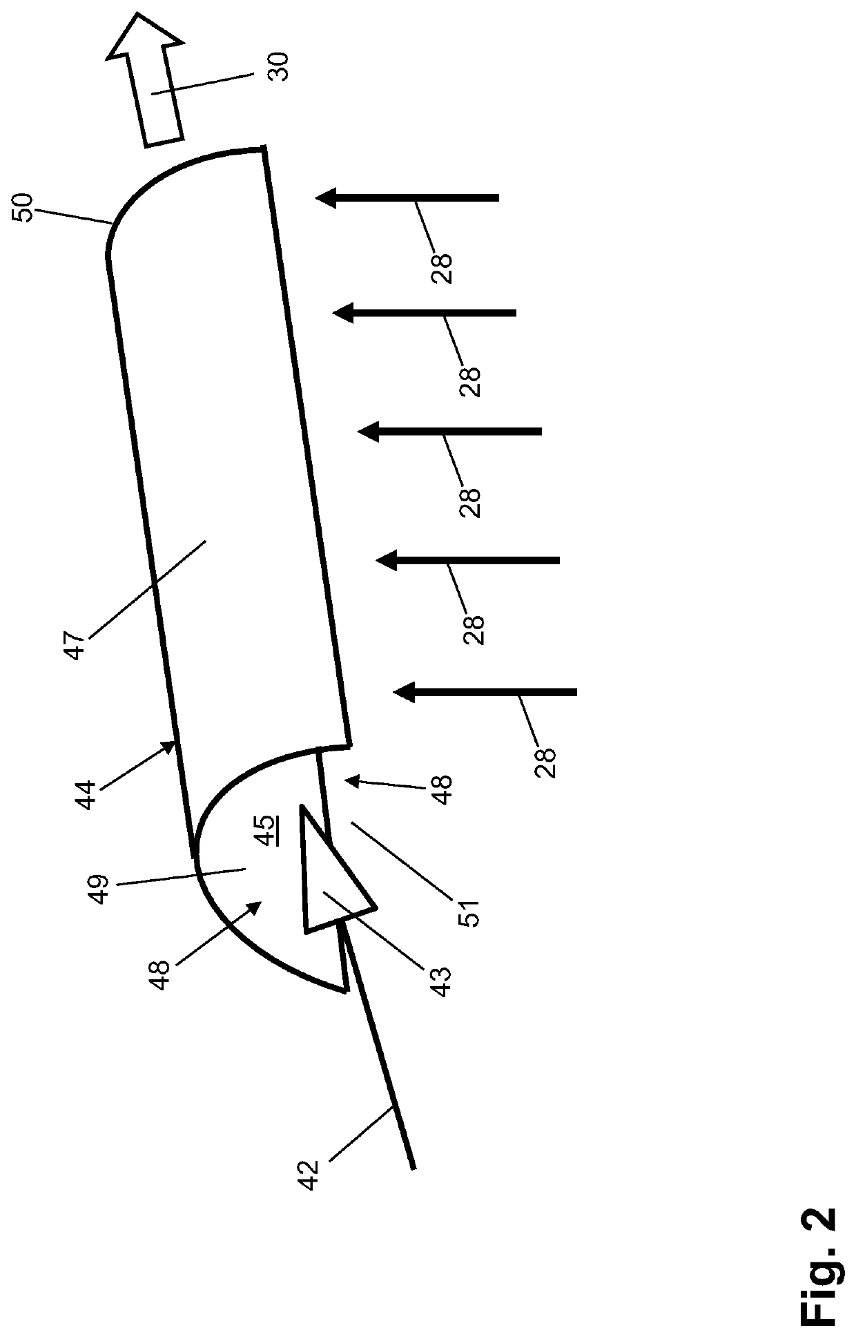
The invention relates, inter alia, to a purging system, which is provided for purging at least one energy source device and / or at least one energy sink device of an energy system, comprising a purging device, which is provided in such a way that the purging device is able to produce a discharge volumetric flow (42) containing hydrogen during a purging process. The aim of the invention is to further advantageously modify a purging system of the type in question in order to avoid explosion hazards due to hydrogen in the discharge volumetric flow after a purging process, by means of economical measures of simple design. This aim is achieved, according to the invention, in that the purging system has a mixing device (44) downstream of the purging device in the flow direction of the discharge volumetric flow (42), which mixing device is provided for mixing the discharge volumetric flow (42) with an air volumetric flow (28), in particular an exhaust air volumetric flow, and that the mixing device (44) has a wall (47), which delimits a defined open thorough-mixing space (45) for the mixing of the discharge volumetric flow (42) with the air volumetric flow (28), the wall (47) delimiting only a subregion of the thorough-mixing space (45), and the region of the mixing device (44) not delimited by the wall (47) forming an entry region (48) for the two volumetric flows.

Description

REFERENCE TO PENDING PRIOR PATENT APPLICATIONS[0001]This patent application claims benefit of International (PCT) Patent Application No. PCT / EP2019 / 086014, filed 18 Dec. 2019 by HPS Home Power Solutions GmbH for PURGING SYSTEM AND USE THEREOF IN AN ENERGY SYSTEM, which in turn claims benefit of German Patent Application No. DE 10 2018 133 201.7, filed 20 Dec. 2018.[0002]The two (2) above-identified patent applications are hereby incorporated herein by reference.FIELD OF THE INVENTION[0003]The present invention first relates to a purging system for purging components of an energy system according to the preamble of the independent claim 1. Furthermore, the invention relates to an energy system according to the preamble of the independent claim 11. Finally, the invention also relates to a method for operating a purging system in an energy system as well as to a special use of a mixing device of a purging system.BACKGROUND OF THE INVENTION[0004]Energy systems of the generic type are al...

Claims


Application Information

Patent Timeline
IPC IPC(8): H01M8/04223C25B15/08
CPCH01M8/04231C25B15/08C25B1/04C25B15/00Y02E60/36Y02E60/50
Inventor HIERL, ANDREASSCHÖNFELDT, RENALDOSCHNEIDER, GUNNARSCHULTE, JONAS
Owner HPS HOME POWER SOLUTIONS GMBH
Learn More