
Enclosed Torque Controlled Electric Actuator and Method

Pending Publication Date: 2022-04-14
PREMIUM OILFIELD TECH LLC
View PDF0 Cites 0 Cited by
  • Summary
  • Abstract
  • Description
  • Claims
  • Application Information

AI Technical Summary

Benefits of technology

This patent presents an actuator that can control positions of equipment such as chokes and valves based on changes in pressure or torque. It is compact and can be used in various environments with limited space. The actuator has a motor, controller, and torque sensor assembly, among others. It can control the equipment autonomously without the need for constant communication with a remote controller and can safely shut down if communication is lost. Overall, this actuator enables efficient and safe operation in various environments.

Problems solved by technology

There are several challenges to using an actuator due to the extreme conditions of a high degree of fluctuations in the well bore flow and pressure, an explosive environment, and a need for a small footprint on a crowded drilling rig.
These control methods are generally adept at holding a constant pressure but has difficulties tracking pressure changes.
Alternatively, a pressure balanced control system for an actuator can respond with more speed and track pressure changes better, but has difficulties responding at lower pressure ranges (less than 300 psi) and making precise pressure control changes.
A second challenge is the harsh, explosive environment in which MPD operates.
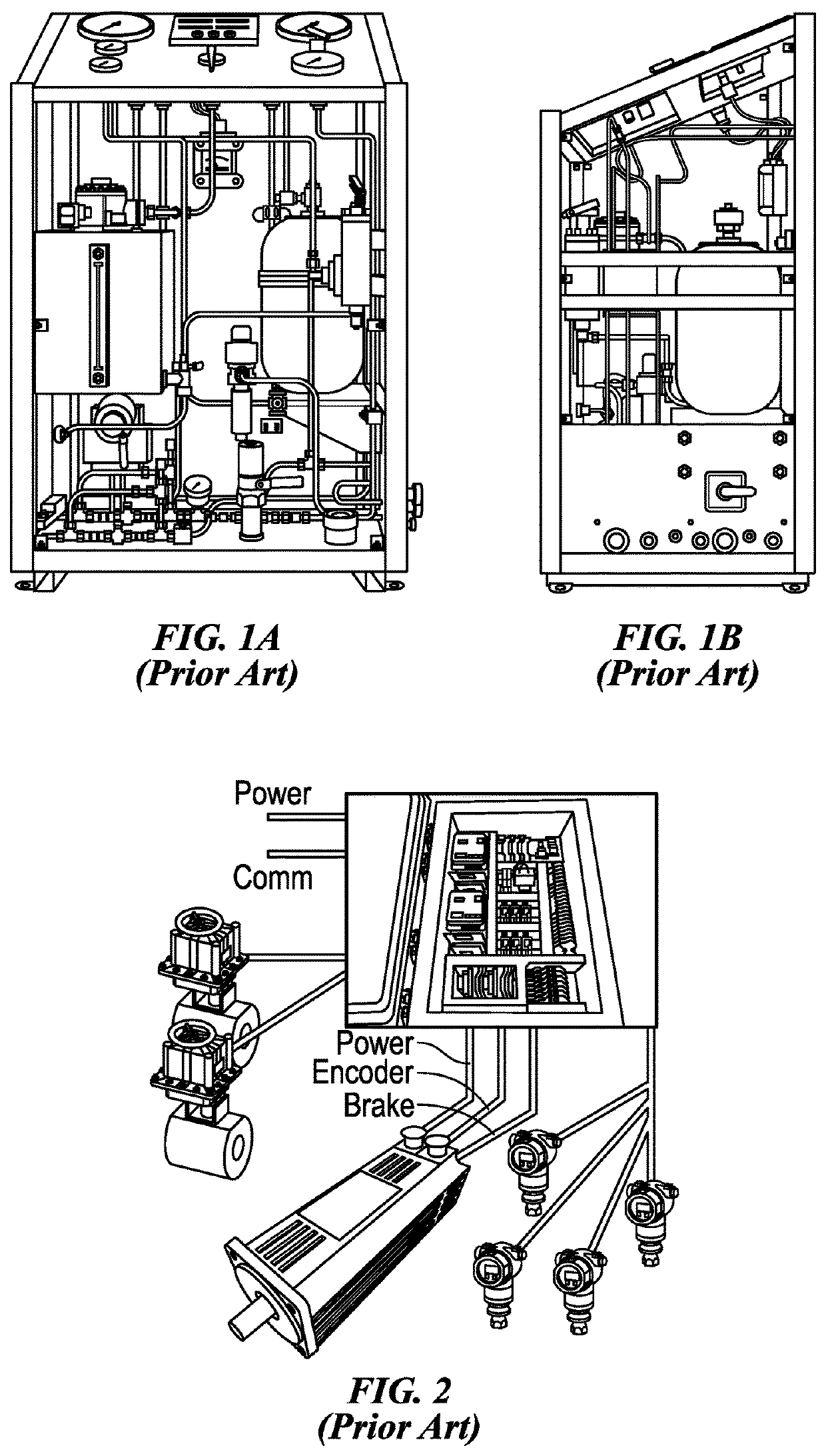
However, the HPU has its own challenges including hydraulic leaks and safety issues as well as a large footprint on or adjacent to the drilling rig.
Combining the equipment into a single enclosure heretofore has not been possible due to the internal heat load in a sealed explosion proof container overheating the components.
However, the separate enclosures require numerous electrical connections between the components and increases the amount of failure points as well as the risk of sparks and explosions.
With limited space on a drill rig or adjacent thereto, a large footprint is impractical.
Heretofore, such a unit has been thought to be impractical and potentially unachievable by those with ordinary skill in the art.

Method used


Image

  • Enclosed Torque Controlled Electric Actuator and Method
  • Enclosed Torque Controlled Electric Actuator and Method
  • Enclosed Torque Controlled Electric Actuator and Method

Examples


Embodiment Construction

[0028]The Figures described above and the written description of specific structures and functions below are not presented to limit the scope of what Applicant has invented or the scope of the appended claims. Rather, the Figures and written description are provided to teach any person skilled in the art how to make and use the inventions for which patent protection is sought. Those skilled in the art will appreciate that not all features of a commercial embodiment of the inventions are described or shown for the sake of clarity and understanding. Persons of skill in this art will also appreciate that the development of an actual commercial embodiment incorporating aspects of the present disclosure will require numerous implementation-specific decisions to achieve the developer's ultimate goal for the commercial embodiment. Such implementation-specific decisions may include, and likely are not limited to, compliance with system-related, business-related, government-related, and othe...


PUM


Abstract

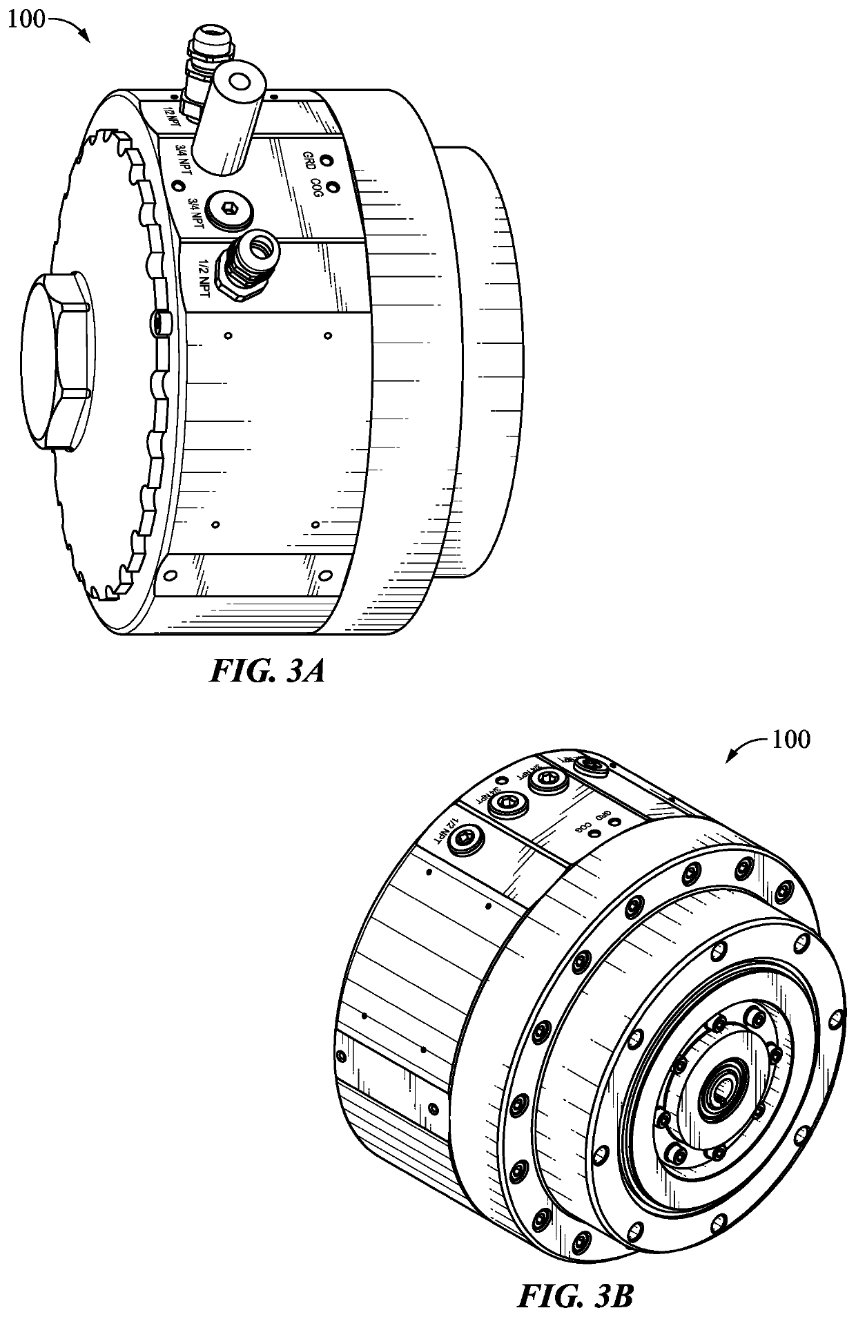
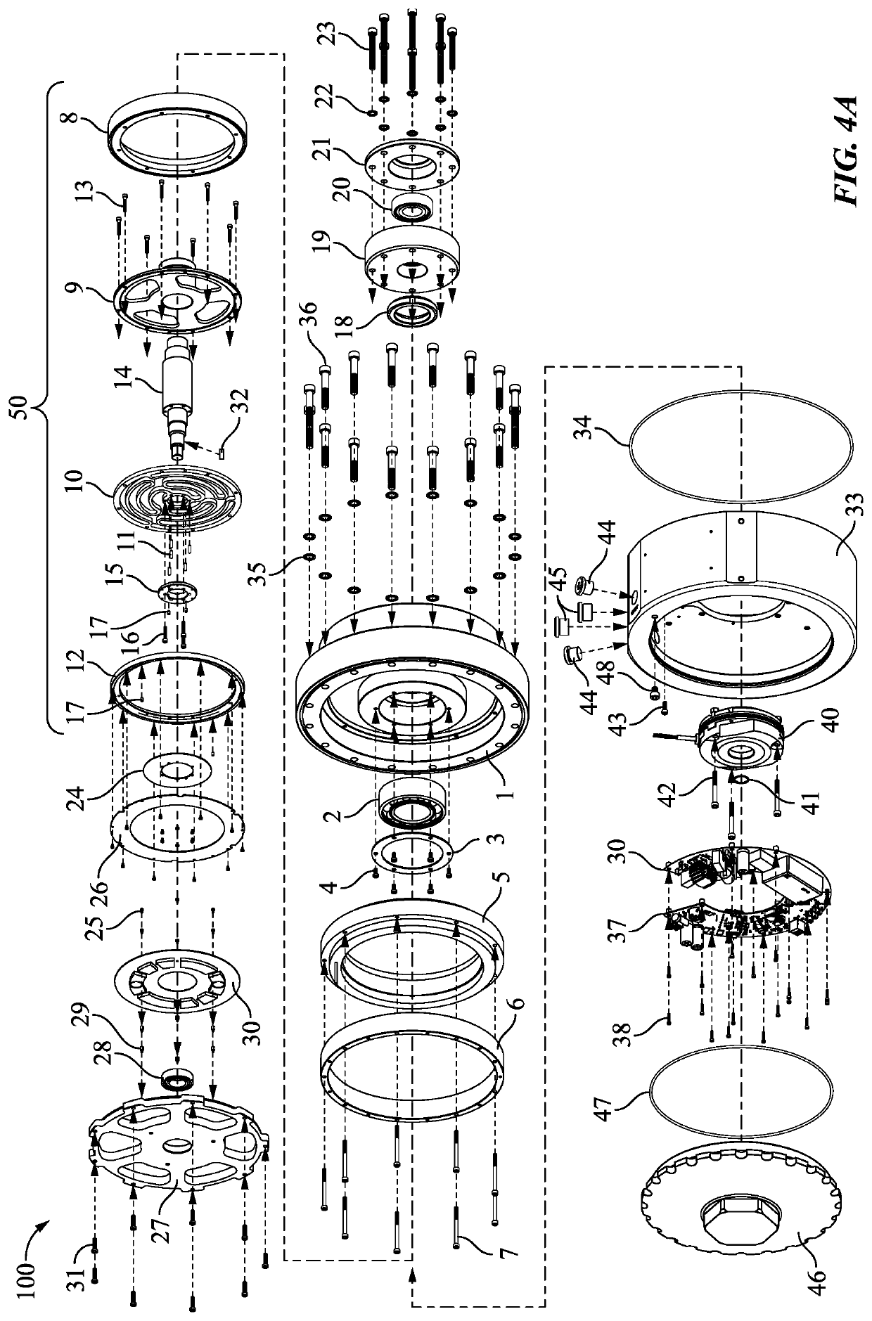
The present disclosure provides an actuator and related method of use that can change and control positions of chokes, valves, and other rotational equipment in response to changes in either pressure, torque, or a combination thereof. The actuator with associated integrated components including a servo motor, motor controller, torque sensor assembly, encoder, holding brake, and onboard controls can be encased in a sealed explosion proof rated enclosure for deployment on a drilling rig or other explosive environments with a small footprint suitable for space limited locations. Pressure applied over a known area, such as a choke plug, is converted to torque and can be repeated regardless of flow rate, temperature, fluid type, or density. The torque sensing ability advantageously can quickly respond to fluid changes and make large steps to different set points with accuracy. The onboard controls can control the actuator autonomously without constant communication with a remote controller.

Description

CROSS REFERENCE TO RELATED APPLICATIONS[0001]This application claims the benefit of U.S. Provisional Ser. No. 63 / 091,780, filed Oct. 14, 2020, and is incorporated fully herein by reference.STATEMENT REGARDING FEDERALLY SPONSORED RESEARCH OR DEVELOPMENT[0002]Not applicable.REFERENCE TO APPENDIX[0003]Not applicable.BACKGROUND OF THE INVENTIONField of the Invention[0004]The disclosure generally relates to an apparatus and method of actuating rotatable equipment and controlling a rotatable position of the equipment based on a torque load. More specifically, the disclosure relates an actuator that can change and control positions of chokes, valves, and other rotational equipment in response to changes in either pressure, torque, or a combination thereof.Description of the Related Art[0005]Managed Pressure Drilling (MPD) is an adaptive drilling method with a goal of controlling the annular pressure within narrow limits throughout a wellbore. After determining the downhole pressure environ...

Claims


Application Information

Patent Timeline
IPC IPC(8): E21B34/06H02K5/136E21B21/10
CPCE21B34/066E21B34/16E21B21/103H02K5/136H02K7/14H02K5/10H02K11/24H02K11/33H02K2211/03E21B34/025
Inventor RICHARD, NEAL C.HULSE, AARON
Owner PREMIUM OILFIELD TECH LLC
Learn More