
Method and system for performing fault diagnosis by bearing noise detection

Active Publication Date: 2022-03-31
AB SKF
View PDF1 Cites 4 Cited by
  • Summary
  • Abstract
  • Description
  • Claims
  • Application Information

AI Technical Summary

Benefits of technology

The present invention provides a method and system for performing fault diagnosis by detecting bearing noise. This approach allows for automatic fault detection without the need for detailed bearing information, resulting in increased accuracy and efficiency. The system can use a generalization capability to detect bearing noise and applies this technique to a range of bearing types.

Problems solved by technology

However, there is a strong correlation between noise and bearing type; for example, different bearing types exhibit differences in bearing dimensions, material and grease, etc., and noise varies because of this.
Thus, a trained detection model for a particular type of bearing cannot be used for other new types of bearing directly.
Another problem with typical bearing noise detection models is that detection is completely dependent on certain key parameters of the bearing, such as fault frequency (BPFI, BPFO, etc.) and relatively stable and accurate rotation speed information.
However, in some cases, information of these parameters is very difficult to collect, e.g. information relating to bearing type is lacking or bearing speed information is lacking.
This not only wastes time and costs, but also cannot support rapid expansion in an ever increasing number of new applications.
In addition, in cases where bearing type and speed information is absent, specialized personnel need to perform diagnosis manually, or diagnosis needs to be performed with very simple diagnosis logic (e.g. RMS threshold or trend); thus, detection efficiency and detection precision are relatively low.

Method used


Image

  • Method and system for performing fault diagnosis by bearing noise detection
  • Method and system for performing fault diagnosis by bearing noise detection
  • Method and system for performing fault diagnosis by bearing noise detection

Examples


Embodiment Construction

[0023]It should be understood that the following description of the presented embodiments is merely intended for illustrative purposes, without being restrictive. The division of examples in the functional blocks, modules or units shown in the drawings should not be interpreted as meaning that these functional blocks, modules or units must be implemented as physically separate units. The functional blocks, modules or units that are shown or described may be implemented as independent units, circuits, chips, functions, modules or circuit elements. One or more functional blocks or units may also be implemented in a common circuit, chip, circuit element or unit.

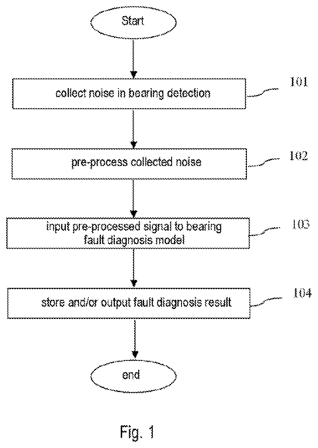
[0024]FIG. 1 shows schematically a flow chart for a method for performing fault identification by detection of bearing noise according to one or more embodiment of the present invention.

[0025]Referring to FIG. 1, in S103, noise in bearing detection can be collected by means of a sensor, e.g. one or more vibration sensor; the noi...


PUM


Abstract

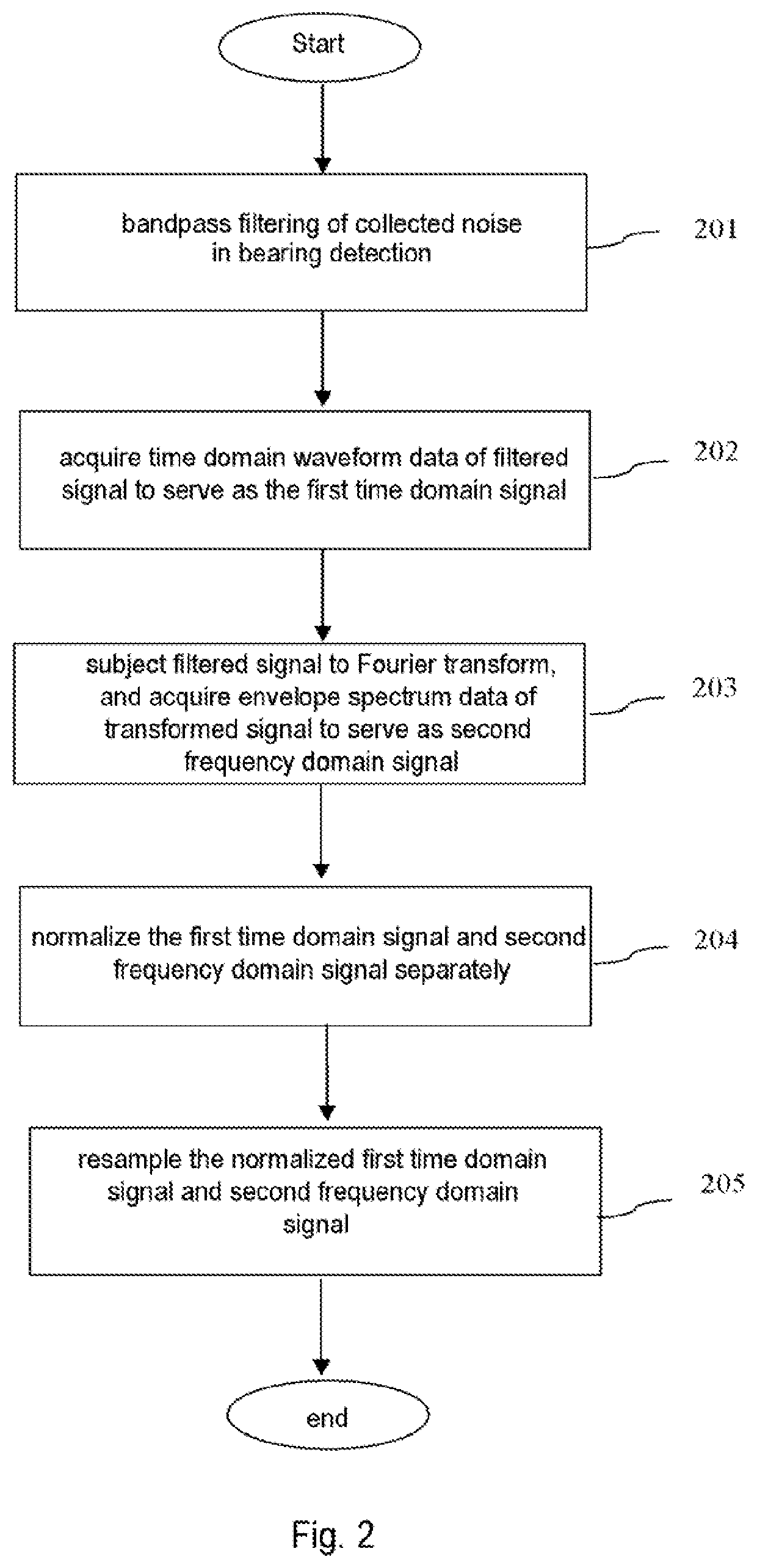
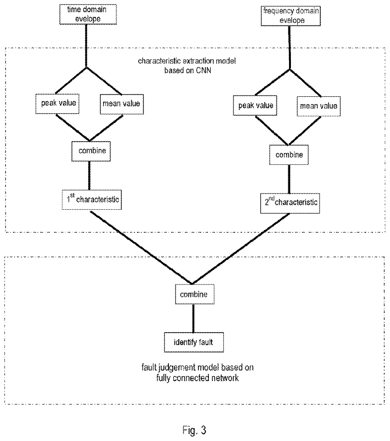
The present disclosure provides a method and system for performing fault diagnosis by bearing noise detection. The method provides: collecting noise in bearing detection, the noise comprising bearing noise and operating condition noise; subjecting the collected noise to pre-processing, to obtain a first time domain signal and a second frequency domain signal; and inputting the first time domain signal and second frequency domain signal to a bearing fault diagnosis model. The bearing fault diagnosis model includes a characteristic extraction model and a fault discrimination model, the characteristic extraction model subjects the first time domain signal and second frequency domain signal to characteristic extraction separately to obtain a first characteristic associated with a time domain shock peak and a second characteristic associated with a fault frequency peak. Moreover, the fault discrimination model combines the first characteristic and second characteristic, and performs fault discrimination on the basis of a combined characteristic.

Description

CROSS-REFERENCE TO RELATED APPLICATIONS[0001]This application claims priority to Chinese patent application no. 202011051999.4, filed Sep. 29, 2020, the contents of which is fully incorporated herein by reference.TECHNICAL FIELD[0002]The present invention relates to the field of bearing noise detection, and in particular to a method and system for performing fault diagnosis by bearing noise detection.BACKGROUND ART[0003]Bearing noise is a key parameter in bearing quality control; certain early-stage bearing defects can be detected by bearing noise detection in the production line. However, there is a strong correlation between noise and bearing type; for example, different bearing types exhibit differences in bearing dimensions, material and grease, etc., and noise varies because of this. Thus, a trained detection model for a particular type of bearing cannot be used for other new types of bearing directly.[0004]Another problem with typical bearing noise detection models is that det...

Claims


Application Information

Patent Timeline
IPC IPC(8): G01M13/045G01H17/00
CPCG01M13/045G01H17/00G01H1/003
Inventor CHENG, GANGLIU, LINHUI
Owner AB SKF
Learn More