
Double Vision Endotracheal Tube Installation System

Inactive Publication Date: 2008-07-24
CHEN TIEN SHENG
View PDF3 Cites 34 Cited by
  • Summary
  • Abstract
  • Description
  • Claims
  • Application Information

AI Technical Summary

Benefits of technology

[0007]It is an objective of the present invention to provide an endotracheal tube installation system with an enhanced view.
[0008]It is another objective of the present invention to provide an endotracheal tube installation system which has two image pickup apparatuses. Said endotracheal tube installation system is capable of transmitting images wirelessly so as to increase the precision and efficiency of the intubation.
[0012]Also, the display used in the invention may be two separate monitors displaying the first image and the second image individually; alternatively, the display may also be a single monitor displaying the first image and the second image simultaneously or by manual switch. Thereby, users may get a better understanding of the patient's upper airway and, more importantly, carry out the intubation with higher efficiency and precision.

Problems solved by technology

However, the aforementioned approach fails to fully satisfy practical needs.
Thus, neither the condition of the patient's upper airway nor the position of the trachea can be known by the anaesthetists, with the result that they can only rely on personal experience and skill during the intubation.
In addition, since the anatomical structures of different patients vary significantly, an intubation system applying only one image pickup apparatus may fail to satisfy the needs of different cases.

Method used


Image

  • Double Vision Endotracheal Tube Installation System
  • Double Vision Endotracheal Tube Installation System
  • Double Vision Endotracheal Tube Installation System

Examples


Embodiment Construction

[0021]To make this invention more understandable to examiners, several preferred embodiments are disclosed and described hereafter.

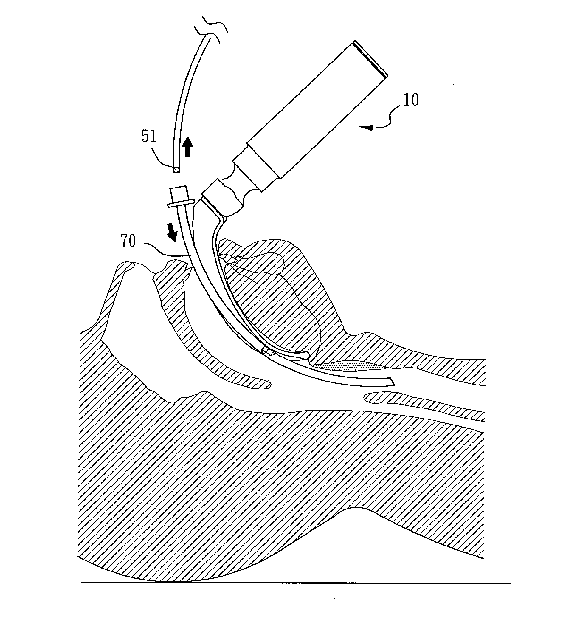
[0022]Please refer to FIGS. 3A and 3B, wherein FIG. 3A is an illustrative diagram showing the second image-capturing unit of the present invention encompassed by an endotracheal tube, and FIG. 3B is an illustrative diagram showing the application of the endotracheal tube installation system of the present invention to perform intubation. The endotracheal tube installation system 1 of the present invention mainly comprises a laryngoscope 10, a tracheoscope 50, an endotracheal tube 70, and at least one display 60. The laryngoscope 10 comprises a handgrip 20, a blade 30 connected to the handgrip 20, and a first image-capturing unit 40 installed on the blade 30 for capturing a first image. The endotracheal tube 70 is a hollow tube encompassing the second image-capturing unit 51 of the tracheoscope 50, which is used for capturing a second image. In addition, ...


PUM


Abstract

A double vision endotracheal tube installation system is disclosed, said system comprising: a laryngoscope, comprising a handgrip and a blade, wherein the blade comprises a first image-capturing unit for capturing a first image; a hollow endotracheal tube; a tracheoscope, comprising a second image-capturing unit for capturing a second image, said second image-capturing unit being wrapped in the endotracheal tube; and at least one display for displaying said first image and second image.

Description

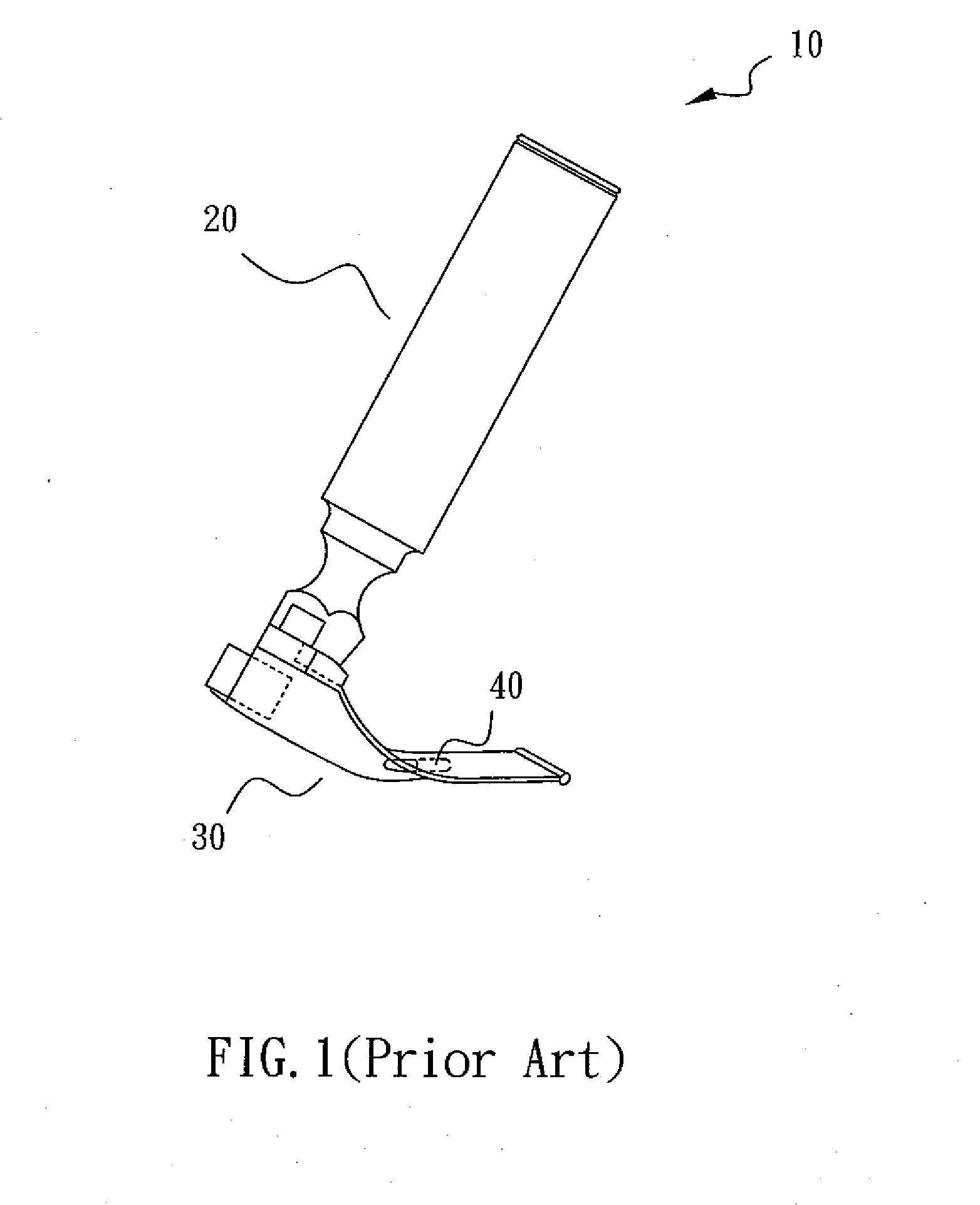
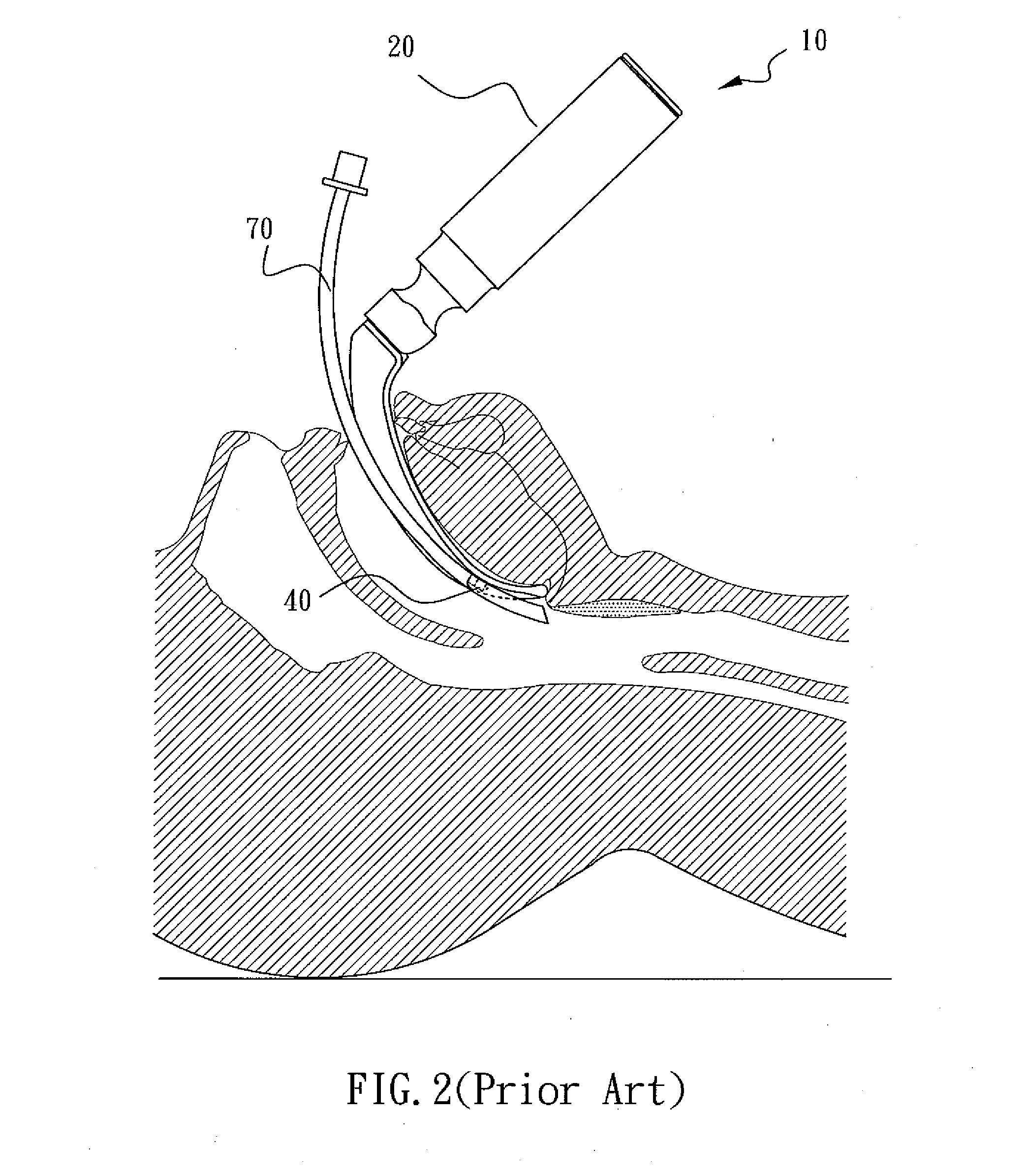
BACKGROUND OF THE INVENTION[0001]1. Field of the Invention[0002]The present invention relates to an endotracheal tube installation system, more particularly to an endotracheal tube installation system capable of providing a dual view[0003]2. Description of the Related Art[0004]Endotracheal intubation is a critical means for maintaining the breathing function of a patient under general anaesthesia. In most cases, to prevent the occurrence of hypoxia, the anaesthetist must complete the intubation by inserting an endotracheal tube into the patient's trachea in a very short period of time to provide oxygen thereinto promptly. Therefore, it is extremely important for anaesthetists to perform the intubation efficiently.[0005]Practically, to intubate quickly, most anaesthetists use a laryngoscope as a means to observe the condition of a patient's upper airway. Please refer to FIG. 1. An early laryngoscope 10 mainly consists of a handgrip 20 and a blade 30, wherein the blade may further com...

Claims


Application Information

Patent Timeline
IPC IPC(8): A61B1/267
CPCA61M16/0488A61B1/267A61M16/0495
Inventor CHEN, TIEN-SHENG
Owner CHEN TIEN SHENG
Learn More