
Method and system for adjustable coating using magnetron sputtering systems

Pending Publication Date: 2022-01-27
INTERPANE ENTWICKLUNGS UND BERATUNGSGESELLSCHAFT MBH & CO KG
View PDF1 Cites 0 Cited by
  • Summary
  • Abstract
  • Description
  • Claims
  • Application Information

AI Technical Summary

Benefits of technology

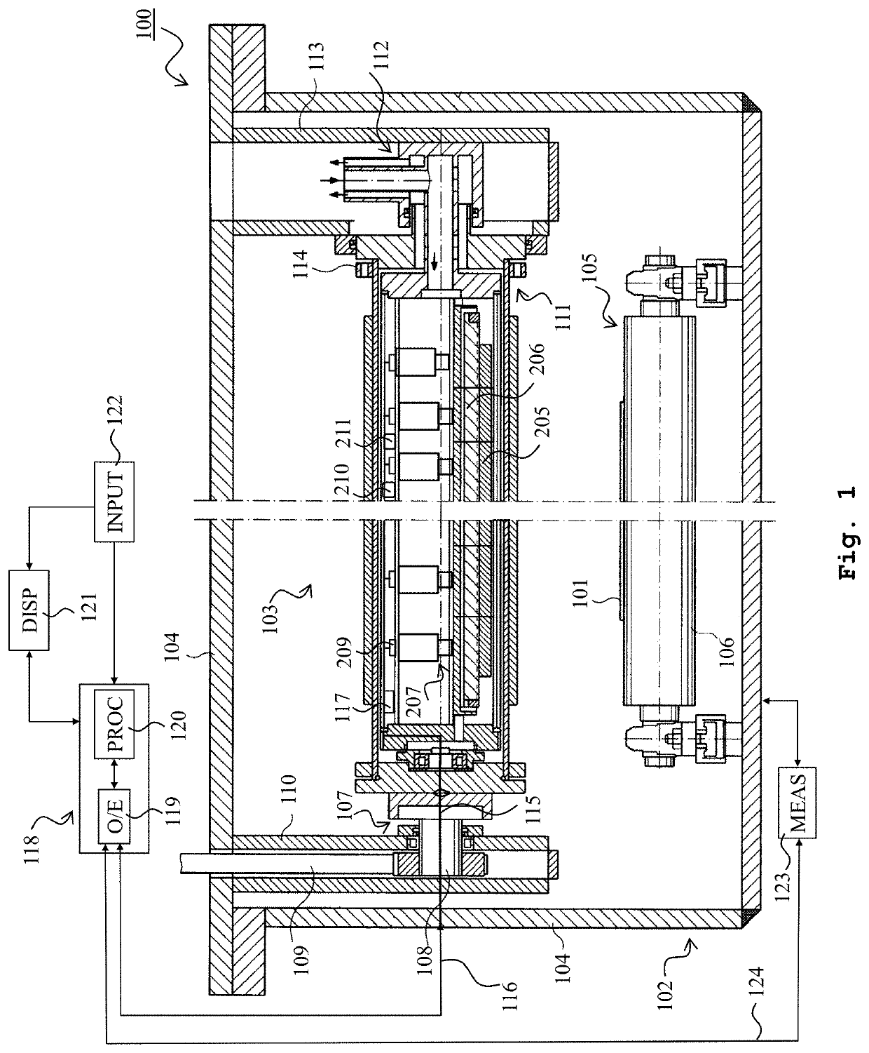
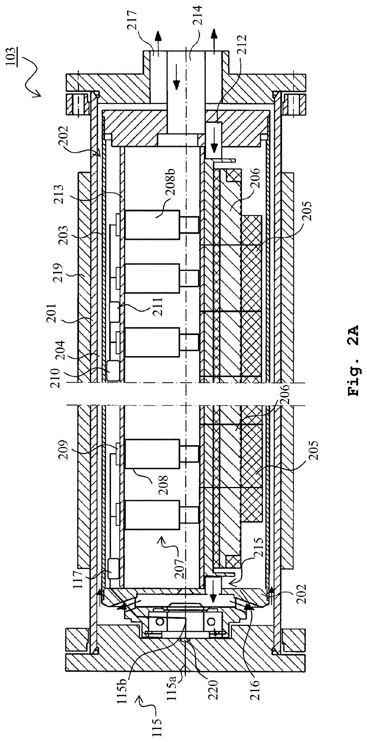
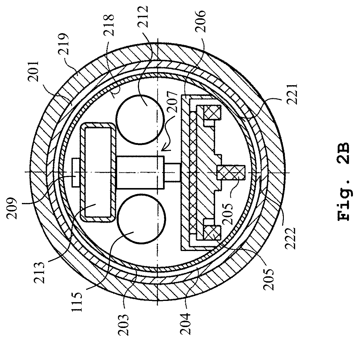
The patent is about a technique that allows for precise control of magnetic field intensity and shape at specific positions in a magnetron sputtering apparatus. This is achieved by manipulating individual magnets and yokes, which allows for direct adjustment of coating profiles across complex substrates during operation. This results in better efficiency, saving time and reducing operation costs.

Problems solved by technology

Control of coating uniformity with high precision during operation has a direct and crucial impact on substrate functionality and process costs.
The above-mentioned document, nevertheless, has the drawback that the shape of the magnet bar structure as a whole is modified by the actuation mechanisms.
This restrains the precise control of the magnetic field shape and intensity in a specific location and therefore limits the possibility to precisely control the plasma intensity and the resulting coating profile which ultimately restricts the prospect of coating onto non-planar substrates.

Method used


Image

  • Method and system for adjustable coating using magnetron sputtering systems
  • Method and system for adjustable coating using magnetron sputtering systems
  • Method and system for adjustable coating using magnetron sputtering systems

Examples


Embodiment Construction

[0042]The present invention will be described with respect to particular embodiments and with reference to certain drawings but the invention is not limited thereto. In the description and in the claims, the indefinite article a or an does not exclude a plurality. Furthermore, the terms first, second and the like in the description and in the claims, are used for distinguishing between similar elements and not necessarily for describing a sequence, either temporally, spatially, in ranking or in any other manner. It is to be understood that the terms so used are interchangeable under appropriate circumstances and that the embodiments of the invention described herein are capable of operation in other sequences than described or illustrated herein.

[0043]Moreover, the terms top, under and the like in the description and the claims are generally employed for descriptive purposes and not necessarily for comprehensively describing exclusive relative positions. It is to be understood that ...


PUM

PropertyMeasurementUnit
Thicknessaaaaaaaaaa
Magnetic fieldaaaaaaaaaa
Transmissionaaaaaaaaaa

Abstract

A method and a system for adjustable coating on a substrate using a magnetron sputtering apparatus are provided. The method comprises the steps of providing a magnetron assembly which comprises a plurality of magnets attached to a plurality of yokes and a plurality of actuating mechanisms (208), each operatively coupled to at least one of the plurality of yokes. The method further comprises automatically determining individual positions of each of the plurality of yokes of the magnetron assembly on the basis of at least one parameter, and adjusting individually positions of each of the plurality of yokes of the magnetron assembly in accordance with the automatically determined individual positions.

Description

TECHNICAL FIELD[0001]The present invention is in the field of magnetron sputtering coating deposition especially with rotating sputtering cathodes. More specifically, the invention refers to a method for coating on a wide variety of substrates, such as glass, having flat and non-flat surfaces, especially presenting a curvature in one or two dimensions.BACKGROUND OF THE INVENTION[0002]Magnetron sputtering with rotary cathodes has long been employed in the glass coating industry owing to its capability to maximize target material usage while creating uniform coating films. Control of coating uniformity with high precision during operation has a direct and crucial impact on substrate functionality and process costs.[0003]The fast growing of thin film technologies leads to advanced coating applications with high requirements and narrow tolerances. These include applications involving non-planar substrates with complex surfaces.[0004]Locally tailoring the magnetic field strength in magne...

Claims


Application Information

Patent Timeline
IPC IPC(8): H01J37/34C23C14/35
CPCH01J37/347C23C14/35H01J2237/332H01J37/3455H01J37/3405H01J37/3473H01J37/32972H01J37/32935C23C14/562
Inventor WAGNER, DOMINIK
Owner INTERPANE ENTWICKLUNGS UND BERATUNGSGESELLSCHAFT MBH & CO KG
Learn More