
Electronic equipment, touch sensor, and position detection apparatus

a technology of position detection and electronic equipment, which is applied in the direction of electric digital data processing, instruments, computing, etc., can solve the problems of inability to cancel the effect of common mode noise, mixed common mode noise, and possible electromagnetic interference with the conductive par

Active Publication Date: 2022-03-24
WACOM CO LTD
View PDF4 Cites 0 Cited by
  • Summary
  • Abstract
  • Description
  • Claims
  • Application Information

AI Technical Summary

Benefits of technology

The patent text describes how to improve the cancellation of noise in a differential amplification system by taking into account the position of conductive parts that may cause noise. This can help to suppress the mixing of common mode noise in the detection signal of a touch sensor, caused by electronic interference with the display panel. Therefore, the technical effect of the patent text is to provide electronic equipment that can more reliably achieve the cancelling effect of noise in a differential amplification system.

Problems solved by technology

Electromagnetic interference with the conductive part may occur, and common mode noise may be mixed into the detection signal of the touch sensor.
However, when the magnitude of noise mixed in the signal of the positive-side electrode and the magnitude of noise mixed in the signal of the negative-side electrode are different in the differential amplification system as in Patent Document 1, the cancelling effect of the common mode noise cannot be obtained, and the influence of noise may be increased by the amplification.

Method used


Image

  • Electronic equipment, touch sensor, and position detection apparatus
  • Electronic equipment, touch sensor, and position detection apparatus
  • Electronic equipment, touch sensor, and position detection apparatus

Examples


first embodiment

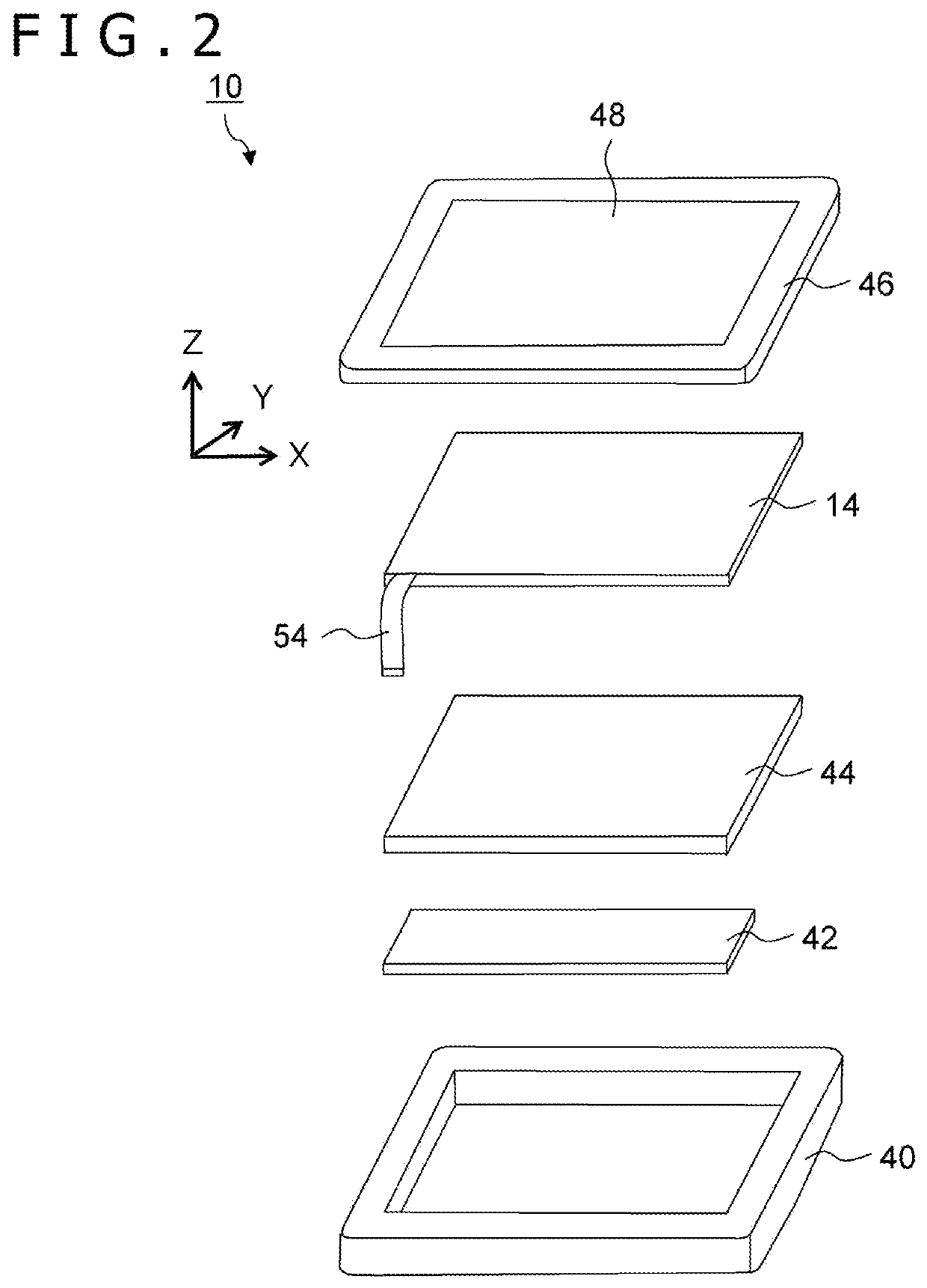
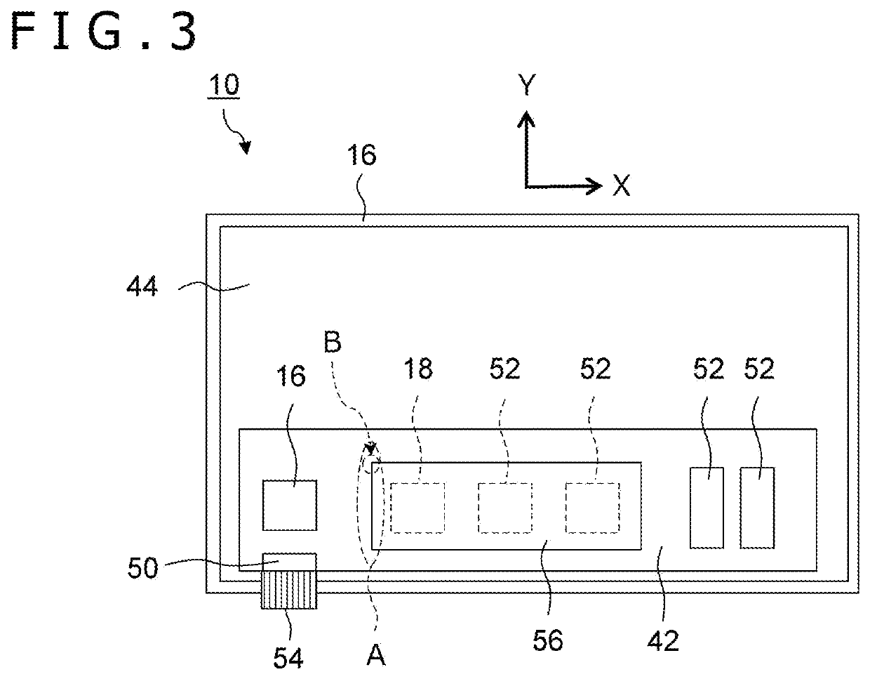
[0031]Electronic equipment according to a first embodiment of the present disclosure will now be described with reference to FIGS. 1 to 8.

[0032]Circuit Configuration of Electronic Equipment 10

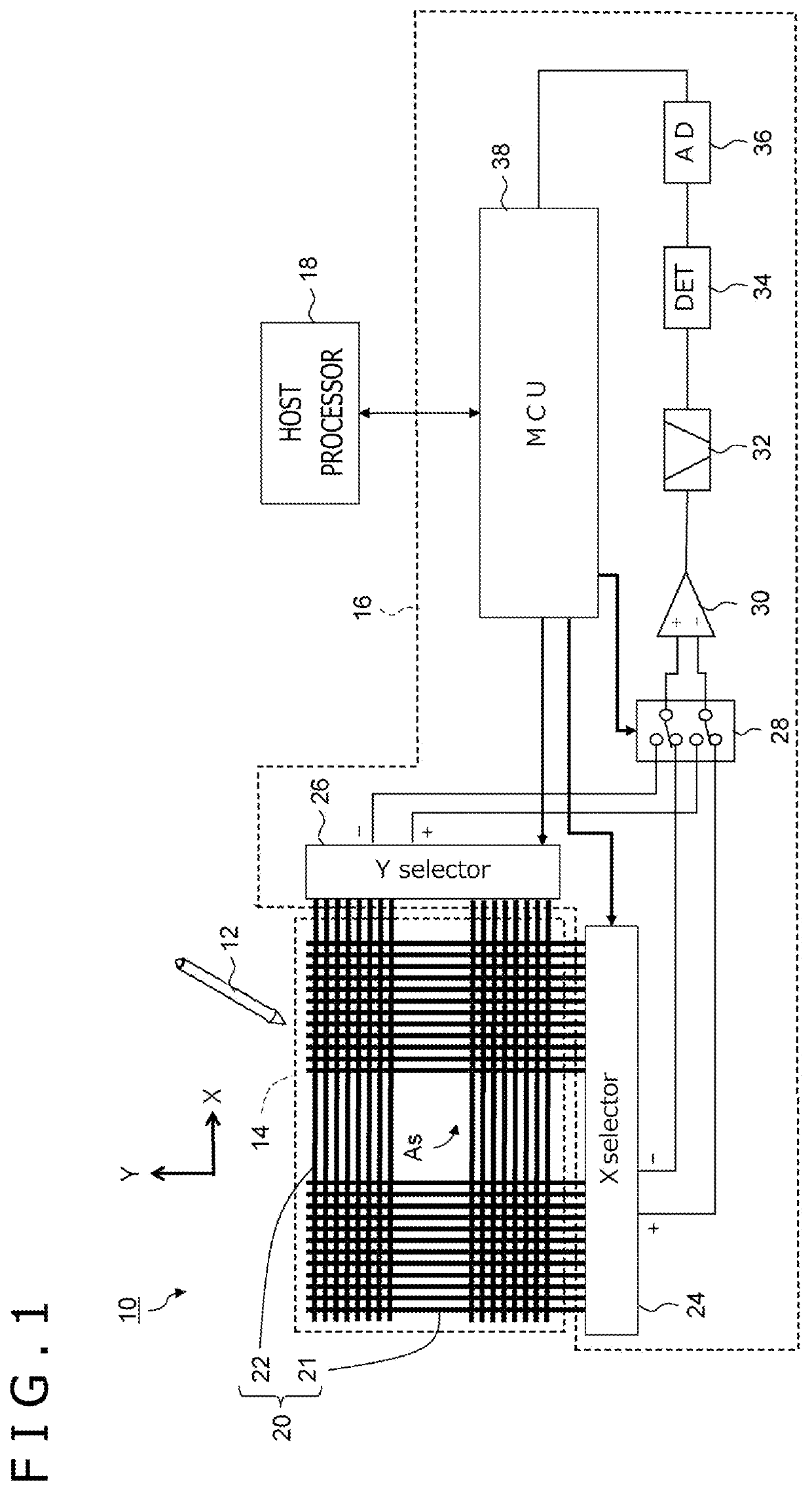
[0033]FIG. 1 is a circuit configuration diagram related to a position detection function of electronic equipment 10 according to the first embodiment of the present disclosure. The electronic equipment 10 may be, for example, a tablet terminal, a smartphone, or a personal computer. A user can grip an electronic pen 12 and move the electronic pen 12 while pressing a pen tip against a touch surface of the electronic equipment 10 to draw pictures or letters in the electronic equipment 10. The electronic pen 12 is, for example, an active electrostatic (AES) or electro magnetic resonance (EMR) stylus.

[0034]The electronic equipment 10 specifically includes a touch sensor 14 that detects the approach of a conductor, such as the electronic pen 12 and a finger of the user, an integrated circuit (IC, her...

second embodiment

[0068]Next, electronic equipment 100 according to a second embodiment will be described with reference to FIGS. 9 to 16B. The same reference signs are assigned to the components or the functions similar to those of the first embodiment, and the description of the components or the functions may be omitted.

[0069]Apparatus Configuration of Electronic Equipment 100

[0070]FIG. 9 is a circuit configuration diagram related to the position detection function of the electronic equipment 100 according to the second embodiment of the present disclosure. The electronic equipment 100 may be, for example, a tablet terminal, a smartphone, or a personal computer, as in the case of the first embodiment (electronic equipment 10 in FIG. 1).

[0071]The electronic equipment 100 specifically includes a touch sensor 102 configured differently from the case of the first embodiment (touch sensor 14 in FIG. 1), a touch IC 104 that controls the touch sensor 102, and the host processor 18 electrically connected ...


PUM


Abstract

Electronic equipment includes a touch sensor including a plurality of electrodes arranged in a plane shape and separated from each other in an array direction, a differential amplifier that amplifies a difference between a positive-side signal and a negative-side signal selectively output from the plurality of electrodes and that outputs the difference, a position detection unit that detects a touch position in a sensor area that is formed by the touch sensor, based on an output signal from the differential amplifier, and a conductive part that is a part made of a conductive material or contains a conductive material and that is arranged to partially overlap the sensor area in plan view. The conductive part is arranged such that an outermost end point thereof in the array direction is positioned on one of the plurality of electrodes.

Description

BACKGROUNDTechnical Field[0001]The present disclosure relates to electronic equipment, a touch sensor, and a position detection apparatus.Description of the Related Art[0002]A position detection apparatus of the so-called “differential amplification system” type is known that amplifies a difference between a signal of a positive-side electrode and a signal of a negative-side electrode of a touch sensor and that outputs the difference, as disclosed in Japanese Patent Laid-Open No. Hei 8-095701 (hereinafter, referred to as Patent Document 1). The difference between the signals from two electrodes parallel to each other can be acquired to achieve an advantageous effect of cancelling common mode noise generated in the same direction.[0003]Electronic equipment includes, in addition to the touch sensor, one or more parts (hereinafter, referred to as a “conductive part(s)”) made of a conductive material or contains a conductive material. Electromagnetic interference with the conductive par...

Claims


Application Information

Patent Timeline
Patent Type & Authority Applications(United States)
IPC IPC(8): G06F3/044G06F3/041G06F3/0354
CPCG06F3/0446G06F3/0412G06F2203/04112G06F3/03547G06F3/04166G06F3/03545G06F3/038G06F3/04182G06F3/0445G06F3/04162G06F3/0442G06F2203/04111G06F2203/04114G06F1/206
Inventor KADOWAKI, JUN
Owner WACOM CO LTD
Learn More