Burner tube

a burner tube and burner technology, applied in the direction of combustion types, lighting and heating apparatus, incinerator apparatus, etc., can solve the problems of reducing the efficiency of burning dirty fuels, affecting the efficiency of combustion, so as to reduce the amount of ash produced, reduce harmful emissions, and reduce the effect of ash production

Pending Publication Date: 2022-03-24
THIESSEN RANDALL J +1
View PDF7 Cites 2 Cited by
  • Summary
  • Abstract
  • Description
  • Claims
  • Application Information

AI Technical Summary

Benefits of technology

The present invention aims to improve upon existing technologies. It provides a system that can efficiently burn dirty fuels such as waste materials or low-grade coal. It can also burn two different types of fuel, minimizing harmful emissions. The system can recycle high-carbon char and reduce ash production. It operates similar to a Bunsen burner, pre-mixing air with fuel before combustion. Overall, the invention produces a compact, efficient, and effective system for waste management and energy production.

Problems solved by technology

Steam boiler / combustor units are well-known, though their use as primary energy generation has been questionable for some time, mainly because of the harmful resultant emissions.
However, the flue gas from the boiler, containing other potentially harmful emissions, is allowed to escape into the atmosphere.
The flue gases from the steam generator are potentially harmful and yet are allowed to escape into the atmosphere.
However, there are currently certain fossil fuels and many types of waste material, such as shingles and used tires, that have fuel potential but are not used because of the high amounts of pollutants created during the combustion process.
In the case of solid waste, if these waste materials are not used, they typically wind up in city dumps or landfills.
However, said method and apparatus were far from perfect, and thus there was a need in the art to optimize the efficiency of the same.

Method used


Image

  • Burner tube
  • Burner tube
  • Burner tube

Examples


Embodiment Construction

[0050]The present disclosure is not to be limited to that described herein. Mechanical, electrical, chemical, procedural, and / or other changes can be made without departing from the spirit and scope of the present invention. No features shown or described are essential to permit basic operation of the present invention unless otherwise indicated.

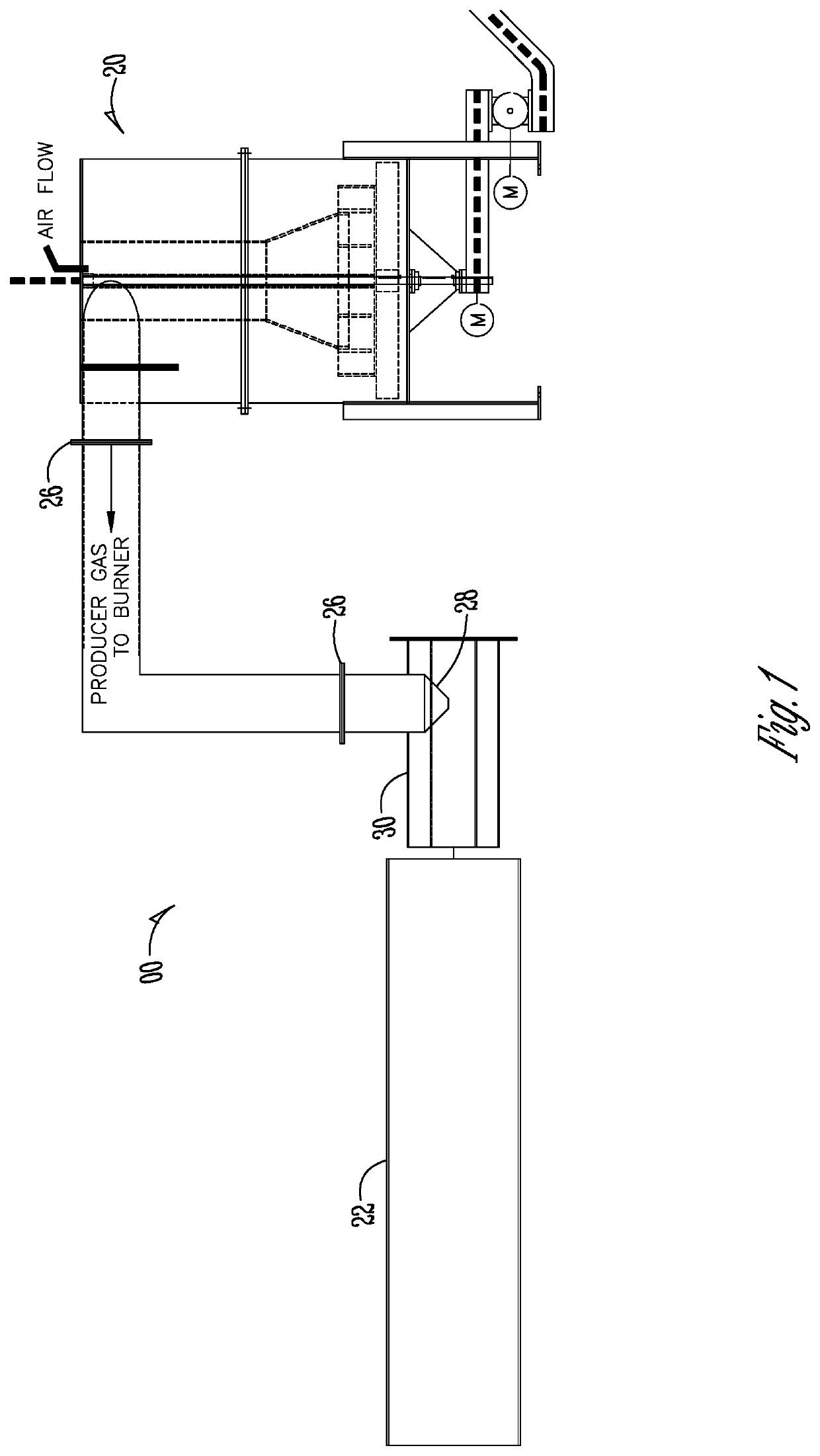
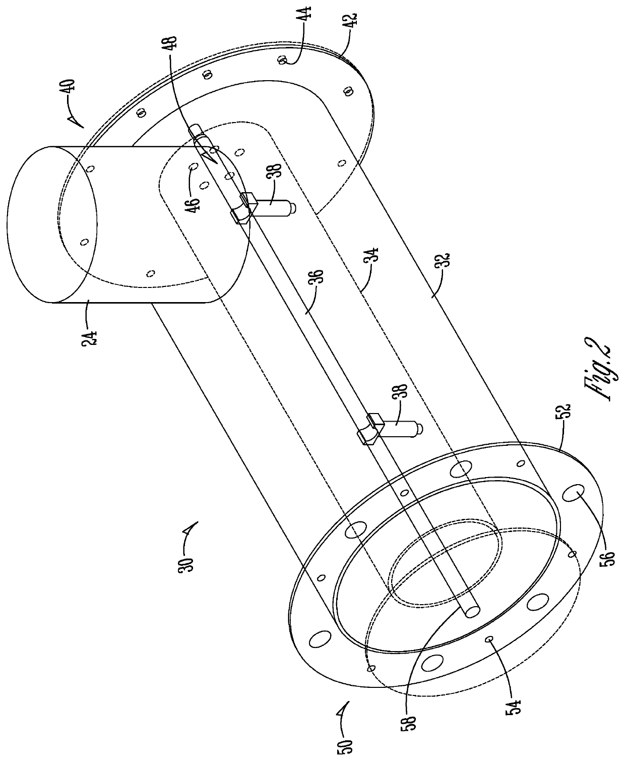
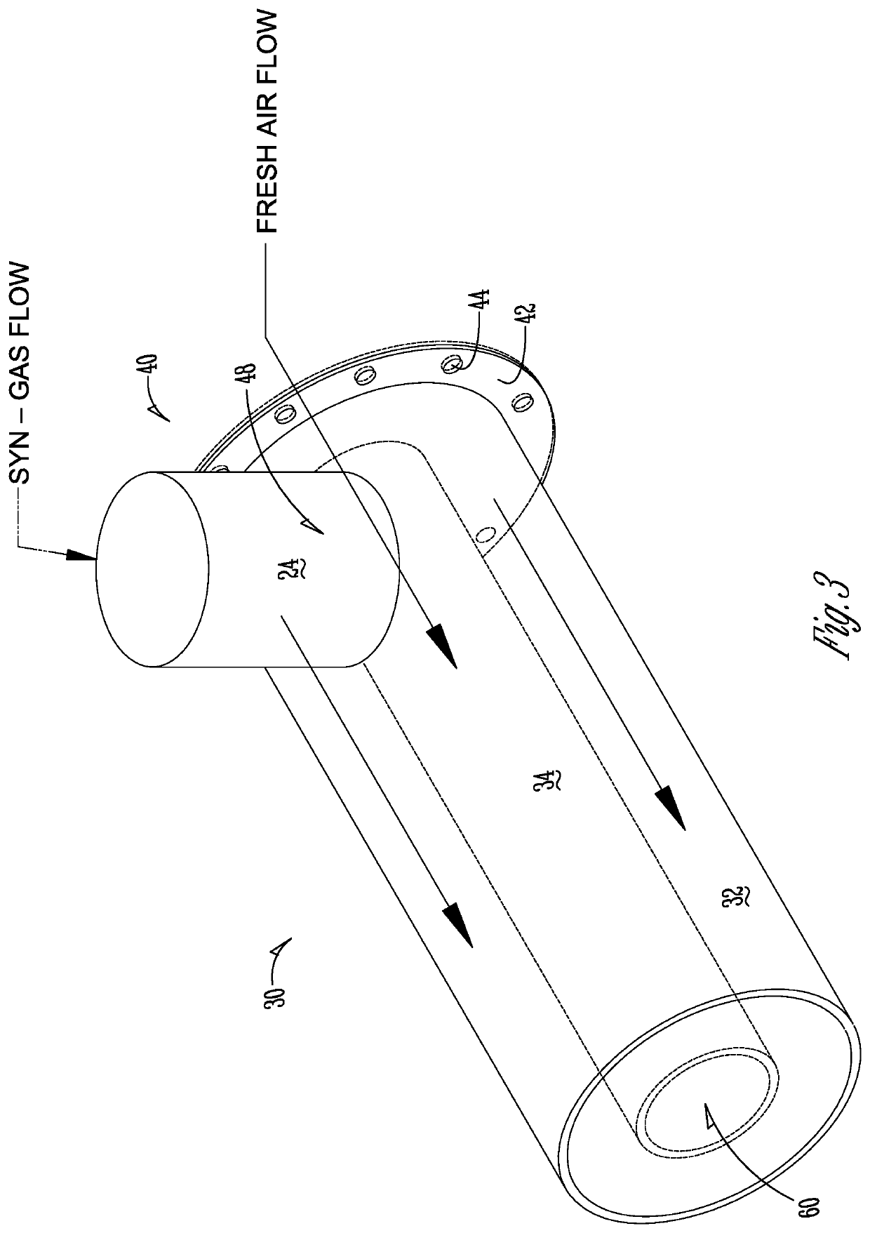
[0051]Referring now to the figures, FIG. 1 shows a system 00 for burning dirty fuel to produce electricity. The system 00 preferably includes at least a gasifier 20, a combustion tube 22, a syn-gas tube 24, and a burner 30.

[0052]Gasification (sometimes called partial combustions) is a process that converts organic- or fossil fuel-based carbonaceous materials into carbon monoxide, hydrogen and carbon dioxide. This is achieved by reacting the material at high temperatures (>700° C.), without combustion, with a controlled amount of oxygen and / or steam. The resulting gas mixture is producer gas (syn-gas). The gas mixture is a fuel. After at leas...


PUM


Abstract

A system and method uses a combustor and gasifier to burn a primary dirty fuel, such as waste materials or high-polluting fossil fuels, and a secondary low-polluting fuel, such as biomass fuels, for co-generation of electricity while reducing harmful emissions. The primary fuel is burned at least partially through the use of an improved burner tube. Dirty exhaust from a combustor is scrubbed by a gasifier by reforming the combustors exhaust gases into a clean-burning producer gas (syn-gas). The secondary fuel and oxygen are added to the dirty exhaust in the gaslifier to create gas, char and ash. The gas powers an engine or turbine that turns a generator, or a boiler, Stirling engine, or Organic Rankine Cycle power plant, and releases a cleaner exhaust.

Description

CROSS REFERENCE TO RELATED APPLICATIONS[0001]This application claims benefit of provisional patent application, U.S. Ser. No. 62 / 930,348, filed Nov. 4, 2019. The provisional patent application is herein incorporated by reference in its entirety, including without limitation, the specification, claims, and abstract, as well as any figures, tables, appendices, or drawings thereof.FIELD OF THE INVENTION[0002]The present invention relates generally to an improved combined combustor and gasifier which cleanses emissions and provides co-generation of power from the burning of waste materials or low-grade coals. More particularly, though not exclusively, the present invention relates to an improved burner tube for use in the combined combustor and gasifier.BACKGROUND OF THE INVENTION[0003]The background description provided herein gives context for the present disclosure. Work of the presently named inventors, as well as aspects of the description that may not otherwise qualify as prior ar...

Claims


Application Information

Patent Timeline
IPC IPC(8): F23C7/00F23C3/00F23D14/02F23D14/62F23G5/027
CPCF23C7/006F23C3/002F23D14/02F23C2900/99011F23G5/0276F23G2201/40F23D14/62Y02E20/12
Inventor THIESSEN, RANDALL J.THIESSEN, JR., LAVOY M.
Owner THIESSEN RANDALL J
Why Eureka
Try Eureka