
Flat roof chemical looping combustion reactor

Pending Publication Date: 2022-03-17
INST FR DU PETROLE +1
View PDF0 Cites 0 Cited by
  • Summary
  • Abstract
  • Description
  • Claims
  • Application Information

AI Technical Summary

Benefits of technology

The aim of the patent is to create a CLC combustion reactor that can minimize the negative effects of turbulence and plug-flow fluidization. These effects can lead to strong fluctuations in pressure, which can damage the reactor and cause temperature and gas / particle mixture non-homogeneity, which negatively affects combustion. The goal is to preserve the reactor's strength and ensure uniform temperature and gas / particle mixing for optimal combustion.

Problems solved by technology

Nevertheless, even if the large bubbles formed do not achieve the diameter of the reactor, they can generate large fluctuations in pressure and vibrations within the bed, typically during their breakage within the bed, on the surface of the bed and on the walls of the reactor.
The plug-flow regime as well as the formation of large bubbles are thus undesirable for several reasons: the mixing of the solid and gas is poorer (less homogeneous), the homogeneity of the temperature of the reactor is no longer ensured, and the strong fluctuations in pressure and vibrations on the walls and the bottom of the reactor are harmful to the mechanical strength of the reactor.
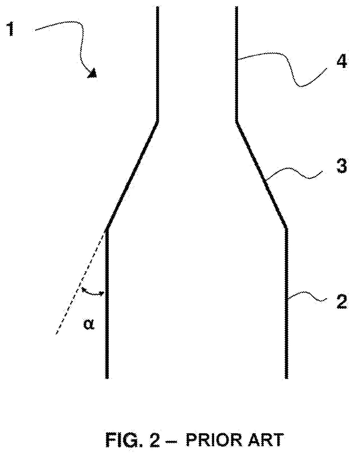
In the case of a fluidized bed reactor connected by its upper part to an elongated pipe of smaller diameter (riser), such as the CLC reactor mentioned above and described in the application WO11151535, the formation of large bubbles can prove to be all the more problematic as the dense agglomerates of solid entrained can in their turn cause a plug-flow phenomenon in the elongated pipe.
Such inserts are not always easy to employ, and this type of reactor may require significant maintenance linked to the possible coking of the inserts.

Method used


Image

  • Flat roof chemical looping combustion reactor
  • Flat roof chemical looping combustion reactor
  • Flat roof chemical looping combustion reactor

Examples


second embodiment

[0126]A combustion reactor 400 according to the invention is illustrated in FIG. 4, and is in all respects identical to the reactor 300 described above in connection with FIG. 3, with the exception of the upper chamber 440, which comprises a penetrating segment 441 in the lower part of the chamber with a height h preferably of between 0.01×H and 0.3×H, H being the height of the lower chamber 320 of the combustion reactor.

[0127]As a nonlimiting example, the height H of the lower chamber 320 can be between 3 m and 40 m, for example be 20 m.

[0128]In the same way, as a nonlimiting example, the height of the upper chamber 440 can be between 3 m and 40 m, for example be 20 m.

[0129]The passage section of the lower chamber to passage section of the upper chamber ratio can be between 2 and 15, and preferentially between 3 and 10.

first embodiment

[0130]The same is true for the dimensions of the upper chamber 340 and lower chamber 320 of the reactor 300 according to the

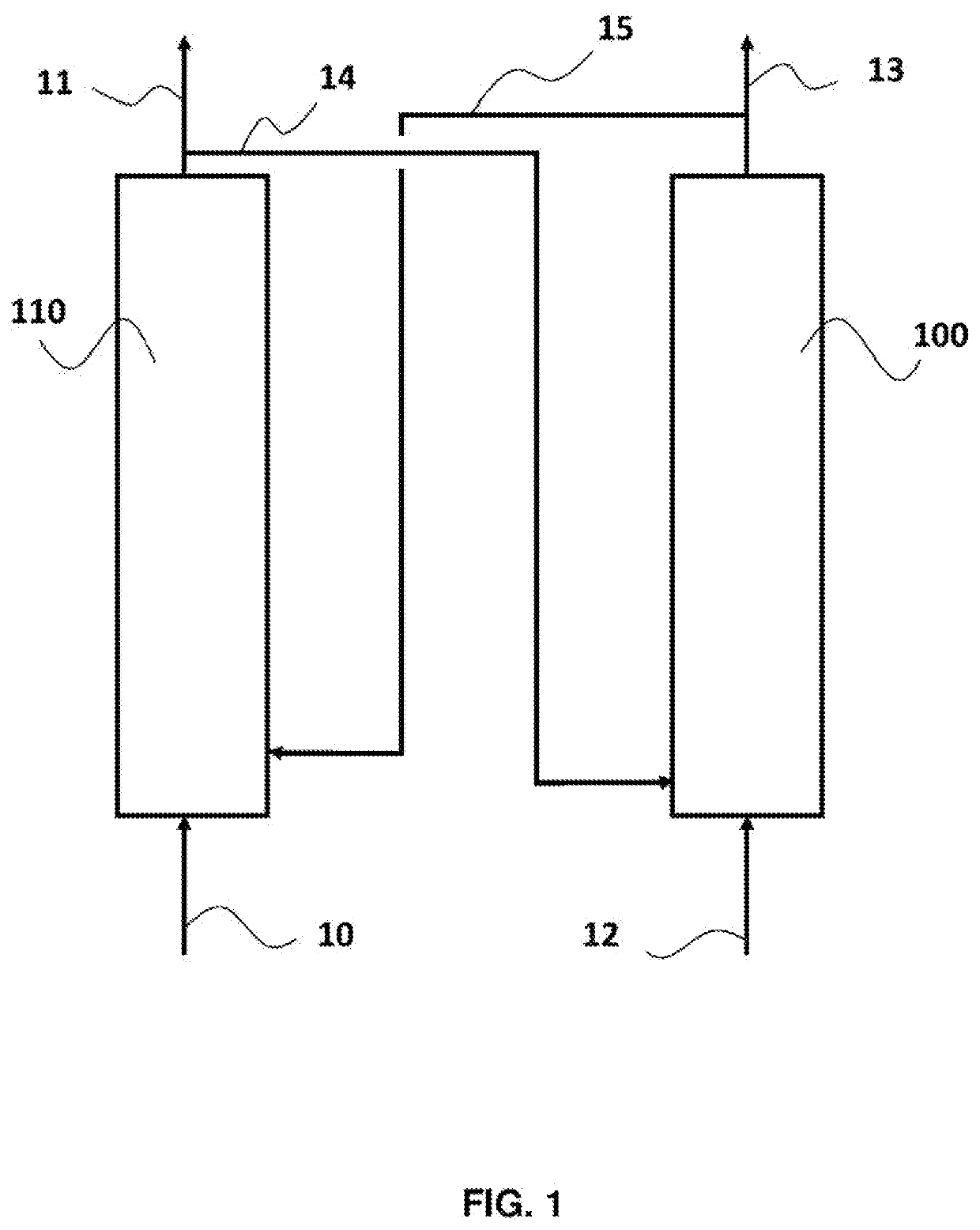
[0131]The present invention also relates to the CLC plant comprising the combustion reactor according to the invention as described above, operating as fluidized bed to carry out the combustion of said hydrocarbon feedstock in contact with the particles of the oxidation / reduction active mass, and comprising the oxidation reactor operating as fluidized bed to oxidize the reduced particles of the oxidation / reduction active mass originating from the combustion reactor by bringing into contact with an oxidizing gas. The details on such a plant have already been given in connection with FIG. 1.

[0132]The present invention also relates to the CLC process employing the combustion reactor according to the invention as described above, and thus comprises the principals the following stages:[0133]particles of an oxidation / reduction active mass are brought into contact wit...


PUM


Abstract

The present invention concerns a combustion reactor (300) for chemical looping combustion (CLC) configured to operate in a fluidised bed, comprising:a lower chamber (320) forming a first reaction zone for the combustion of a hydrocarbon feedstock in the presence of particles of an oxidation-reduction active mass, comprising a first side wall and being configured to include a dense fluidised bed;an elongate upper chamber (340) with smaller passage cross-section than that of the lower chamber, forming a second reaction zone for the combustion of gaseous effluents originating from the combustion in the lower portion, comprising a second side wall and being configured to include a dilute fluidised bed;an intermediate portion (330) connecting the two chambers, and including an inner wall forming a right angle with the side walls of the two chambers. The invention also relates to the facility and the CLC process incorporating such a reactor (300).

Description

TECHNICAL FIELD[0001]The present invention relates to the field of the combustion of hydrocarbon feedstocks by chemical looping oxidation / reduction (CLC) operating as fluidized bed, and more specifically relates to a CLC combustion reactor operating as fluidized bed which is particularly well suited to the combustion of solid or liquid hydrocarbon feedstocks.PRIOR ART[0002]The chemical looping combustion (CLC) process is a process consisting in carrying out oxidation / reduction reactions of an active mass, typically a metal oxide, in order to break the reaction for the combustion of a hydrocarbon feedstock down into two successive reactions:[0003]a first reaction of oxidation of the active mass in contact with an oxidizing gas, typically air, in at least one oxidation zone, and a second reaction of reduction of the active mass in contact with the feedstock, the combustion of which is desired, in at least one combustion zone.[0004]The oxidation / reduction active mass, which gives up a ...

Claims


Application Information

Patent Timeline
IPC IPC(8): F23C10/18F23C10/00
CPCF23C10/18F23C2900/99008F23C10/005F23C99/00Y02E20/34
Inventor CLOUPET, ANNTEBIANIAN, SINAGUILLOU, FLORENTBERTHOLIN, STEPHANETILLAND, AIRYAMBLARD, BENJAMINYAZDANPANAH, MAHDIREDDY KARRI, SURYAKNOWLTON, TEDD
Owner INST FR DU PETROLE
Learn More