Continuously variable transmission

a technology of continuously variable transmission and transmission shaft, which is applied in the direction of gear lubrication/cooling, hoisting equipment, gearing elements, etc., can solve the problems of increasing the size of the continuously variable transmission and deteriorating fuel efficiency

Active Publication Date: 2022-03-10
HONDA MOTOR CO LTD
View PDF6 Cites 0 Cited by
  • Summary
  • Abstract
  • Description
  • Claims
  • Application Information

AI Technical Summary

Benefits of technology

The present disclosure provides a continuously variable transmission that can decrease the flow rate or pressure of oil towards the endless member even when the flow rate or pressure of oil towards the pulley side increases. This is achieved by providing an oil passage that circulates oil to the endless member through the same system as the pulleys, and by using a flow control valve that operates based on the pulley pressure on the downstream side. The transmission also includes a lubricating oil passage with a supply port that can be opened or closed based on the winding diameter of the endless member to optimize lubricating oil supply efficiency. Overall, the transmission has a simple configuration and can effectively control the flow rate or pressure of oil towards the endless member.

Problems solved by technology

However, in such a case, problems such as deterioration of fuel efficiency and an increase in size of the continuously variable transmission may arise.

Method used


Image

  • Continuously variable transmission
  • Continuously variable transmission
  • Continuously variable transmission

Examples


Embodiment Construction

[0021]Next, illustrative embodiments of the disclosure will be described with reference to the drawings. Further, the same reference numerals are given to the same or equivalent parts, and overlapping description thereof is omitted.

[0022][Configuration of Continuously Variable Transmission]

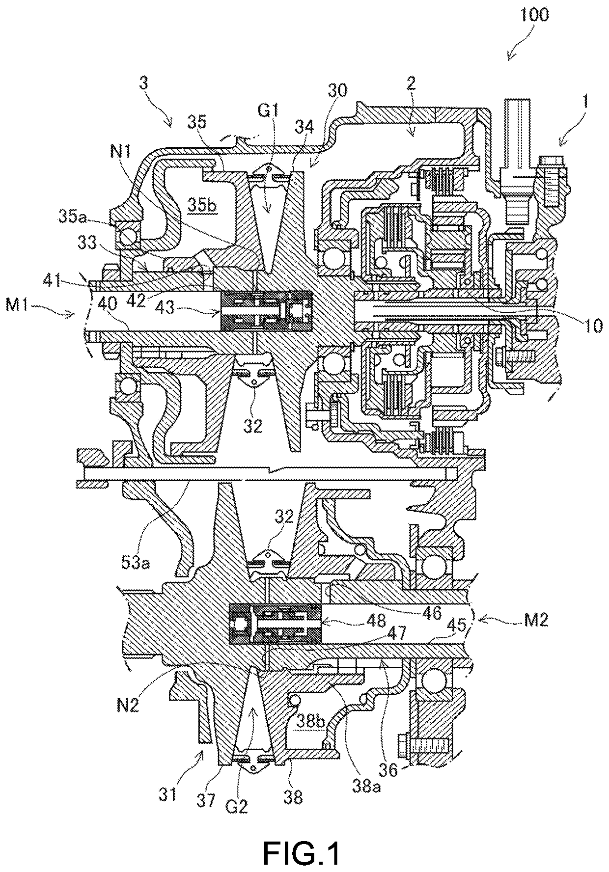
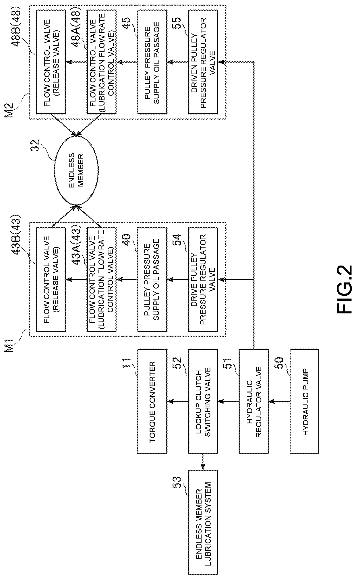
[0023]FIG. 1 is a cross-sectional view illustrating a part of a continuously variable transmission 100 according to the present embodiment. FIG. 2 is a block diagram illustrating a lubrication circuit of the continuously variable transmission 100. The continuously variable transmission 100 is a belt-type continuously variable transmission (CVT) with a pulley structure and can change (i.e., can shift) a gear ratio continuously, as illustrated in FIGS. 1 and 2. The continuously variable transmission 100 is an automatic transmission mounted in a vehicle, for example, a passenger car, and can shift a drive force input from a drive source (not illustrated) side continuously and output the force to a dr...


PUM


Abstract

A continuously variable transmission changes a gear ratio by changing a groove width between the fixed side pulley half body and the movable side pulley half body in each of the driving pulley and the driven pulley using pulley pressure. At least any of a drive shaft of the driving pulley and a driven shaft of the driven pulley includes a pulley pressure supply oil passage for supplying pulley pressure to the movable side pulley half body, a lubricating oil passage provided on a downstream of the pulley pressure supply oil passage to supply oil as a lubricating oil to an endless member, and a flow control valve that is provided between the pulley pressure supply oil passage and the lubricating oil passage and operates according to pulley pressure.

Description

CROSS-REFERENCE TO RELATED APPLICATION[0001]This application claims the priority benefit of Japan application serial no. 2020-151445, filed on Sep. 9, 2020. The entirety of the above-mentioned patent application is hereby incorporated by reference herein and made a part of this specification.BACKGROUNDTechnical Field[0002]The present disclosure relates to a continuously variable transmission.Description of Related Art[0003]A continuously variable transmission using an endless member is known. Oil functioning as a lubricant is supplied to the endless member of such a continuously variable transmission when necessary. In the continuously variable transmission disclosed in Patent Document 1, for example, a required flow rate of a lubricant to be supplied to the endless member is calculated based on a torque input to the continuously variable transmission, the rotational speed of a driving pulley, and a pulley ratio, and a discharge flow rate of an oil pump is set to realize the calcula...

Claims


Application Information

Patent Timeline
IPC IPC(8): F16H61/662F16H55/56F16H57/04
CPCF16H61/66272F16H55/56F16H2061/66295F16H2061/66277F16H57/0434F16H57/0435F16H57/0446F16H57/043F16H57/0489F16H61/0025F16H61/0009F16H2061/0037
Inventor YAGASAKI, TORU
Owner HONDA MOTOR CO LTD
Why Eureka
Try Eureka