Safety device, valve arrangement and method

Pending Publication Date: 2022-03-03
FESTO AG & CO KG
View PDF0 Cites 0 Cited by
  • Summary
  • Abstract
  • Description
  • Claims
  • Application Information

AI Technical Summary

Benefits of technology

This invention aims to improve the safety device's reliability and make it fail-safe. It achieves this by connecting a transmission unit to the voltage supply of the logic voltage zone, which prevents any short-circuit between the two zones. The invention also uses a current limitation element to limit the current flow through the transmission unit and prevent overheating. This results in a safer and reliable safety device.

Problems solved by technology

Conventionally, there is the risk of the transmission unit being able to become damaged, for example by way of too high a current subjection and an overheating which is caused by way of this, and in this case the galvanic separation is lost, so that a voltage from the logic voltage zone can be transmitted into the load voltage zone via the transmission unit, said voltage there effecting an (undesired) activation of the function unit and / or the actuator.

Method used


Image

  • Safety device, valve arrangement and method
  • Safety device, valve arrangement and method
  • Safety device, valve arrangement and method

Examples


second embodiment

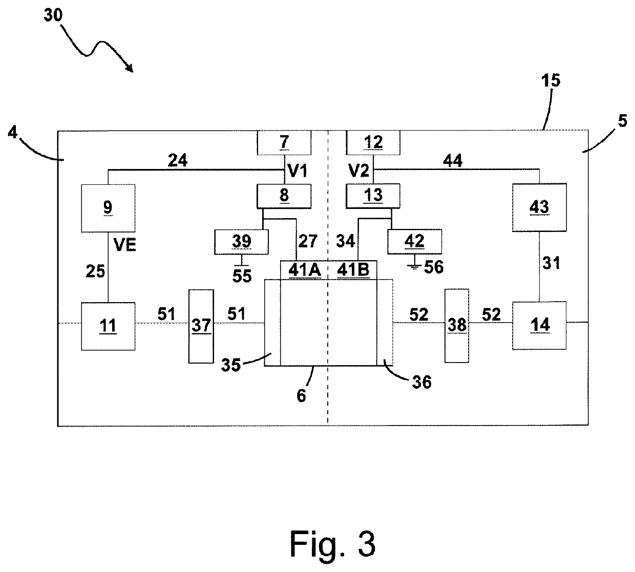
[0059]FIG. 3 shows a safety device 30 according to a The explanations which relate to the safety device 10 preferably also apply to the safety device 30.

[0060]In the safety device 30, the transmission unit 6 in particular is designed as a digital isolator. The transmission unit 6, in particular the digital isolator, is designed as a chip. For example, the transmission unit 6 is a digital isolator, in particular a multichannel digital isolator, for example a four-channel digital isolator. By way of example, the transmission unit 6 is the digital isolator ISO7041 by Texas Instruments.

[0061]The transmission unit 6 has a first bus interface 35 which belongs to the logic voltage zone 4 and a second bus interface 36 which belongs to the load voltage zone 5. The first bus interface 35 and / or the second bus interface 36 in particular are interfaces for a synchronous serial data bus, for example for an SPI. SPI stands for serial peripheral interface. A first signal path 51, for example a bu...

third embodiment

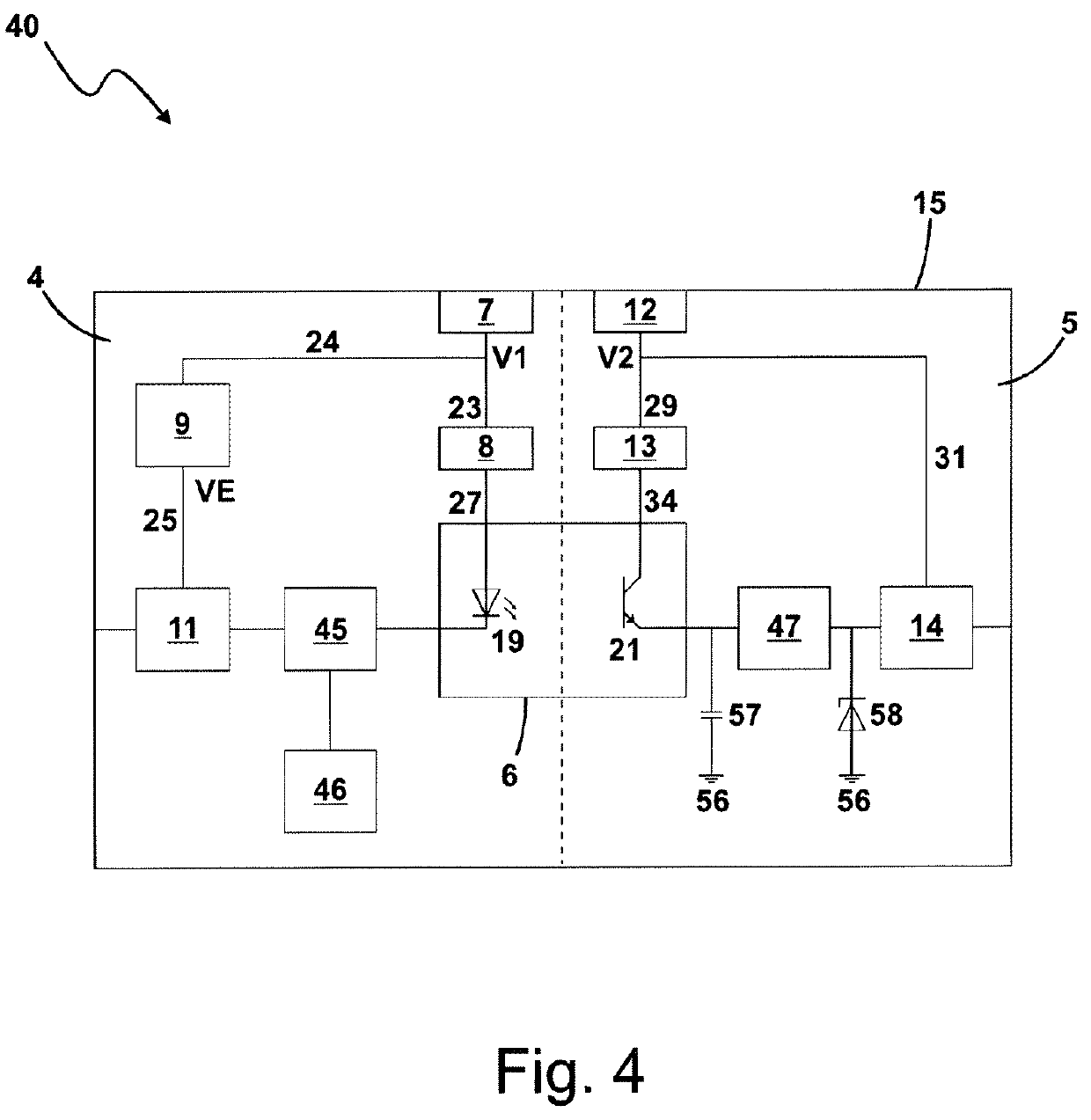
[0075]FIG. 4 shows a safety device 40 according to a The explanations which relate to the safety device 10 preferably also apply to the safety device 40.

[0076]In the safety device 40, the transmission unit 6 is designed as an optocoupler. The first transmission unit section 19 by way of example is designed as an optical transmitter, for example as a light diode or laser diode. The first transmission unit section 19 is supplied with current via the first current limitation element 8. The second transmission unit section 21 by way of example is designed as an optical receiver, for example as a photodiode or as a phototransistor. The second transmission unit section 21 is supplied with current via the second current limitation element 13.

[0077]The logic voltage zone 4 by way of example comprises a transistor 45, for example a bipolar transistor, in particular an npn transistor. The computation unit 11 controls the first transmission unit section 19 via the transistor 45 and, by way of...

fourth embodiment

[0086]FIG. 5 shows a safety device 50 according to a The explanations which relates to the safety device 10 preferably also apply to the safety device 50.

[0087]In the safety device 50, the transmission unit 6 is designed as an optocoupler. The first transmission unit section 19 by way of example is designed as an optical receiver, for example as a photodiode or as a phototransistor. The first transmission unit section 19 is supplied with current via the first current limitation element 8. The second transmission unit section 21 by way of example is designed as an optical emitter, for example as a light diode or laser diode. The section transmission unit section 21 is supplied with current via the second current limitation element 13.

[0088]The logic voltage zone 4 by way of example comprises a pull-up resistor 48, via which the first transmission unit section 19, in particular its output, is connected to the first current limitation element 8. The output of the first transmission un...


PUM


Abstract

A safety device (10, 30, 40, 50), in particular a safety control apparatus and / or a safety diagnosis apparatus, for industrial automation, including a logic voltage zone (4), a load voltage zone (5) which is galvanically separated from the logic voltage zone (4), a transmission unit (6) for transmitting a communication signal between the logic voltage zone (4) and the load voltage zone (5) whilst maintaining the galvanic separation, a first voltage supply connection (7) for providing a first supply voltage (V1) for the logic voltage zone (4) and a first current limitation element (8), wherein the transmission unit (6) is connected on the first voltage supply connection (7) via the first current limitation element (8) and is fed from the first voltage supply connection (7) via the first current limitation element (8).

Description

BACKGROUND OF THE INVENTION[0001]The invention relates to a safety device, in particular to a safety control apparatus and / or to a safety diagnosis apparatus, for industrial automation, comprising a logic voltage zone, a load voltage zone which is galvanically separated from the logic voltage zone, a transmission unit for transmitting a communication signal between the logic voltage zone and the load voltage zone whilst maintaining the galvanic separation, and a first voltage supply connection for providing a first supply voltage for the logic voltage zone.[0002]The load voltage zone in particular serves for the control, in particular the energizing (via current provision), of an actuator, and the logic voltage zone comprises for example a computation unit, in particular a microcontroller which serves for monitoring and / or controlling the load voltage zone and / or the actuator. The safety device for example comprises a module housing, in which the logic voltage zone and the load volt...

Claims


Application Information

Patent Timeline
IPC IPC(8): H03K19/003
CPCH03K19/003F16K31/02F16K37/0025
Inventor HARTMANN, PHILIPPUSSCHULTHEISS, MICHAEL
Owner FESTO AG & CO KG
Why Eureka
Try Eureka