High-voltage apparatus control device

Pending Publication Date: 2022-02-17
SANDEN CORP
View PDF0 Cites 0 Cited by
  • Summary
  • Abstract
  • Description
  • Claims
  • Application Information

AI Technical Summary

Benefits of technology

The present invention relates to a control device for high-voltage apparatuses, which includes an interlock loop for detecting the connection state of a connector and quickly discharging the residual charge in case of disconnection. This device is independent of operating conditions and less susceptible to disturbances, making it reliable and efficient at monitoring and controlling the connection state of a connector. It achieves this by forcibly discharging the residual charge upon detection of disconnection, thus effectively eliminating electric shock and reducing installation space and cost. Additionally, the invention allows for the discharge of residual charge even when the connector is connected, thus minimizing discharge in a normal state. Overall, the invention provides a safer, efficient, and cost-effective solution for controlling high-voltage apparatuses.

Problems solved by technology

If this connector is detached, there is a risk of the occurrence of an accident, such as an electric shock, attributable to the residual charge accumulated in a smoothing capacitor of a control device.

Method used


Image

  • High-voltage apparatus control device
  • High-voltage apparatus control device
  • High-voltage apparatus control device

Examples


first embodiment

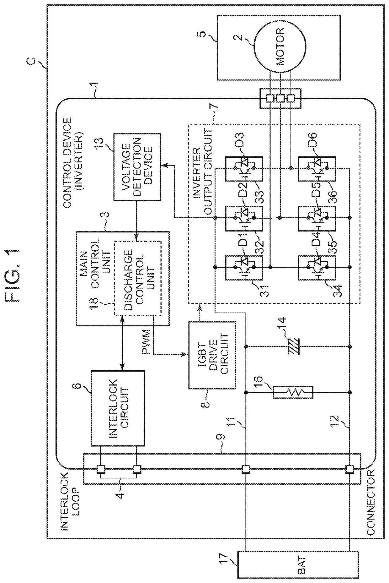
[0035]FIG. 1 illustrates the functional blocks of a control device 1 of an in-vehicle electric compressor C as a high-voltage apparatus to which the present invention is applied, the electric compressor C constituting an air conditioner of a vehicle. The control device 1 of the present invention is a so-called inverter that controls the operation of a motor 2 of the electric compressor C. The motor 2 is contained together with a compression mechanism unit 5 in a housing of the electric compressor C, and the compression mechanism unit 5 is driven by the motor 2. Further, the control device 1 is provided in an inverter storage compartment formed in the housing of the electric compressor C.

[0036]Referring to FIG. 1, the control device 1 of the present embodiment includes a main control unit 3 composed of a microcomputer provided with a microprocessor, an interlock circuit 6 having an interlock loop 4, an inverter output circuit 7 that operates the motor 2, a drive circuit 8 that drives...

second embodiment

[0066]FIG. 5 is a block diagram of a control device 1 of another embodiment of the present invention. In this drawing, components represented by the same reference numerals as those in FIG. 1 have the same or similar functions. In this embodiment, a discharge circuit 43 composed of a resistor 41 and a switch 42 is connected in parallel to a smoothing capacitor 14 between a power line 11 and a ground line 12 of a connector 9.

[0067]Further, in the HV forced discharge control in step S6 of FIG. 4, a discharge control unit 18 of a main control unit 3 in the case of this embodiment closes the switch 42 of the discharge circuit 43 to pass the residual charge accumulated in the smoothing capacitor 14 to the resistor 41 thereby to forcibly discharge the residual charge. In other words, unlike the case of the first embodiment, the residual charge accumulated in the smoothing capacitor 14 is discharged by the discharge circuit 43 rather than being discharged through the windings of the motor ...


PUM


Abstract

To provide a high-voltage apparatus control device capable of judging the connection state of a connector and discharging residual charge in a short time. A control device 1 controls an electric compressor and is provided with an interlock loop 4 annexed to a connector 9 for connecting the electric compressor to an HV battery 17. The control device 1 detects connection / disconnection of the connector 9 on the basis of the state of the interlock loop 4 and forcibly discharges residual charge in an internal smoothing capacitor 14 when disconnection of the connector 9 is detected.

Description

TECHNICAL FIELD[0001]The present invention relates to a control device that controls a high-voltage apparatus, such as an in-vehicle electric compressor.BACKGROUND ART[0002]An electric compressor (high-voltage apparatus) constituting, for example, an air conditioner of a vehicle is connected to a high voltage power supply (HV battery) by a connector (HV connector). If this connector is detached, there is a risk of the occurrence of an accident, such as an electric shock, attributable to the residual charge accumulated in a smoothing capacitor of a control device. Conventionally, therefore, measures have been taken to discharge the residual charge in the smoothing capacitor if the connector is detached and becomes disconnected.[0003]There are a passive method and an active method for discharging the residual charge. Of these, the passive method is a method in which a high power resistor (discharge resistor) is simply connected in parallel with a smoothing capacitor to constantly disc...

Claims


Application Information

Patent Timeline
IPC IPC(8): H02M1/32F04B35/04H02H7/16H02J7/00H02M7/5387H02P23/28
CPCH02M1/322F04B35/04H02H7/16H02P27/06H02M7/5387H02P23/28H02J2207/50H02J7/0029
Inventor JIN, YUNHAIYOSHIDA, HIROSHI
Owner SANDEN CORP
Why Eureka
Try Eureka