
Stator and motor assembly including same

a technology of motor assembly and static motor, which is applied in the direction of dynamo-electric machines, magnetic circuit rotating parts, magnetic circuit shapes/forms/construction, etc., can solve the problems of low efficiency of permanent magnets, low efficiency of electromagnets, and low efficiency of conventional pm vernier motors, so as to improve current density and energy efficiency. , the effect of increasing the torqu

Pending Publication Date: 2022-02-17
DAEGU GYEONGBUK INST OF SCI & TECH
View PDF10 Cites 0 Cited by
  • Summary
  • Abstract
  • Description
  • Claims
  • Application Information

AI Technical Summary

Benefits of technology

The present invention describes a stator and motor assembly with improved energy efficiency and increased torque. This is achieved by designing the stator with openings that change in size along the rotation axis, which allows for better current density. The stator also has salient teeth that create a passage for magnetic flux, allowing for greater torque. The inner surface of the stator core is also inclined at an angle, which maximizes magnetic flux and energy density. However, the invention is not limited to these technical effects.

Problems solved by technology

However, considering that the permanent magnets require specific metals such as rare-earth elements, it can be said that the permanent magnet motors have some deficiencies in terms of fossil fuel depletion and environmental pollution.
However, such a double half-type PM vernier motor has a deficiency in that the permanent magnets lower the efficiency of electromagnets, because the polarities formed by the electromagnets of the stator alternate, whereas the polarities of the permanent magnets are constant.
Such a double half-type PM vernier motor has improved performance compared to the conventional PM vernier motor, but the efficiency thereof is not remarkably higher than the conventional PM vernier motor.
As a result, a magnetic flux short circuit occurs between the permanent magnets and the electromagnets, which lowers the efficiency of the motor.

Method used


Image

  • Stator and motor assembly including same
  • Stator and motor assembly including same
  • Stator and motor assembly including same

Examples


Embodiment Construction

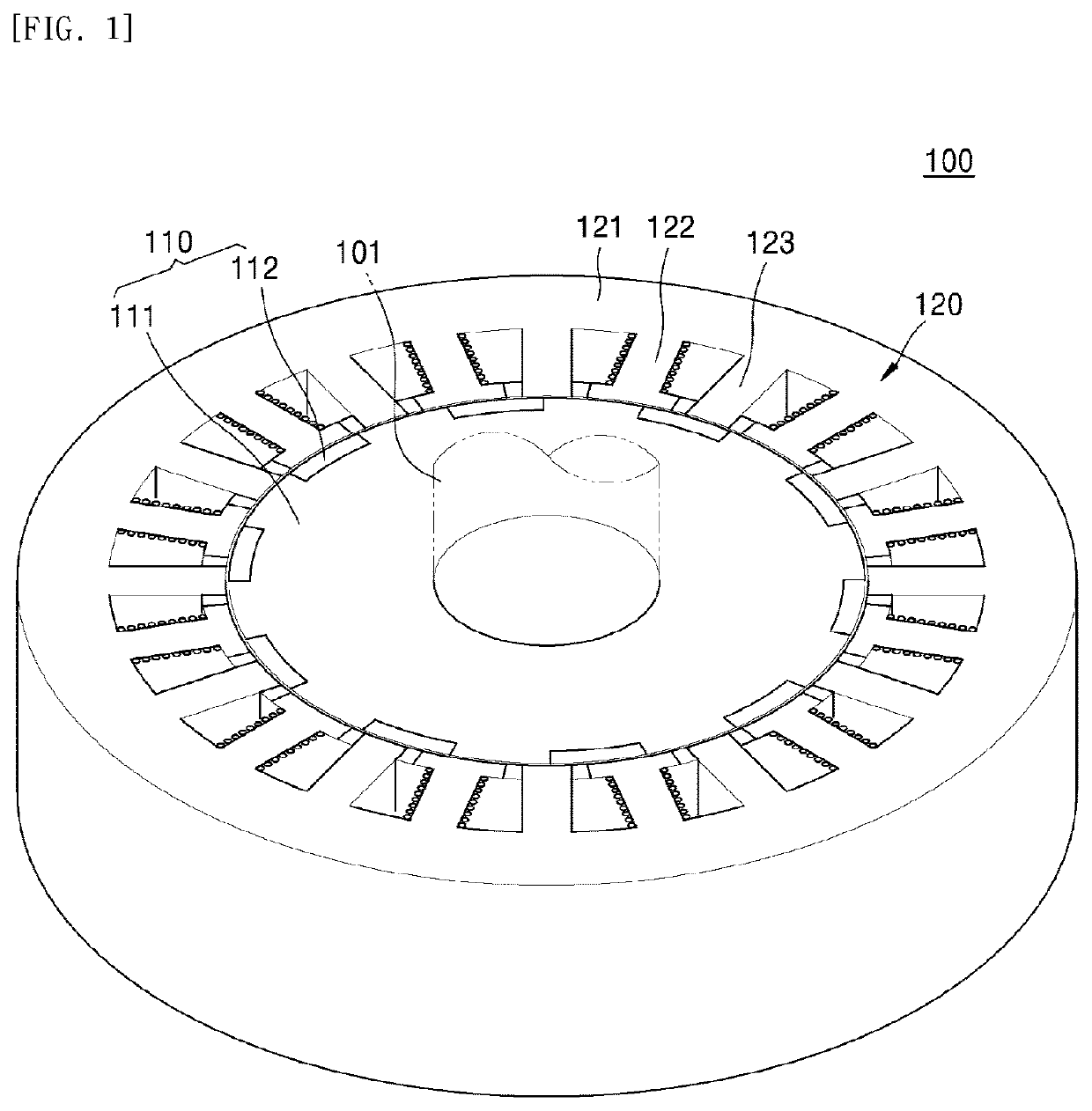
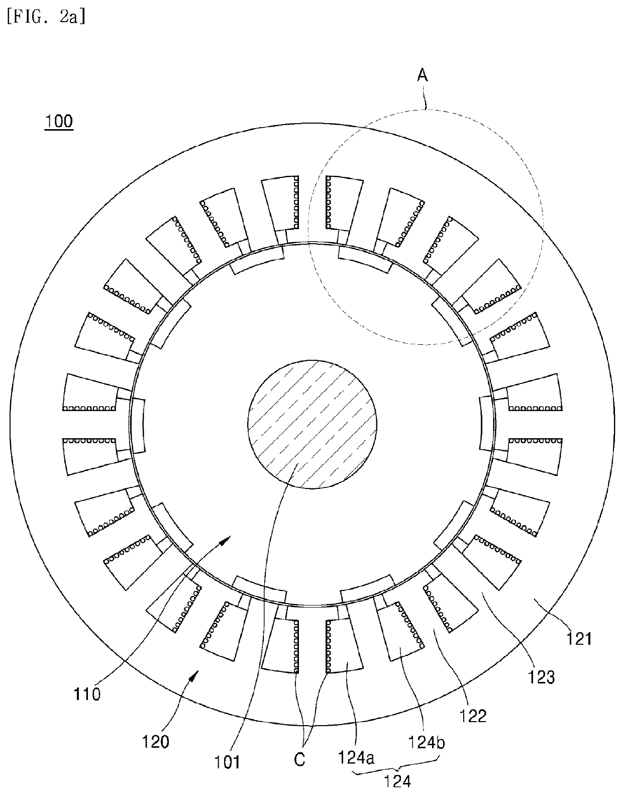
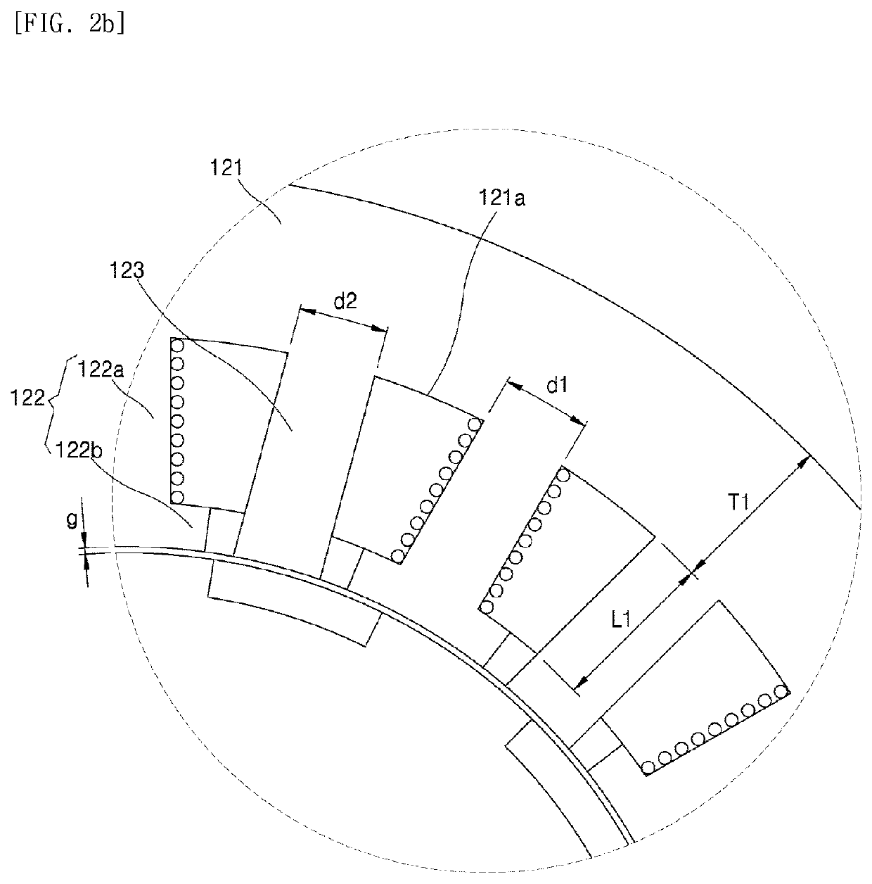
[0018]According to an aspect of the present invention, a stator may include: a stator core disposed outside a rotor core and having an inner surface which is inclined with respect to a rotation axis of the rotor; a plurality of coil-wound teeth extending from the inner surface of the stator core towards the rotation axis, wherein a coil is wound around each of the plurality of coil-wound teeth; and openings formed by sidewalls of the plurality of coil-wound teeth and the inner surface of the stator core, wherein a cross-sectional area of the openings may change along a direction of the rotation axis.

[0019]A thickness of the stator core in a radial direction may linearly increase along one direction of the rotation axis.

[0020]A surface area of the openings measured on one surface of the stator and a surface area of the openings measured on the other surface of the stator may be different from each other.

[0021]The stator may further include a plurality of salient teeth around which th...


PUM


Abstract

The present invention provides a stator and a motor assembly including the same. The stator includes: a stator core disposed outside a rotor core and having an inner surface inclined with respect to a rotation axis of a rotor; a plurality of coil-wound teeth extending from the inner surface of the stator core towards the rotation axis, wherein a coil is wound around each of the plurality of coil-wound teeth; and openings formed by sidewalls of the plurality of coil-wound teeth and the inner surface of the stator core, wherein a cross-sectional area of the openings changes along a direction of the rotation axis.

Description

TECHNICAL FIELD[0001]The present invention relates to a stator and a motor assembly including the same.BACKGROUND ART[0002]A motor is a machine that obtains rotational force from electric energy, and includes a stator and a rotor. The rotor is configured to interact electromagnetically with the stator, and is rotated by a force acting between a magnetic field and a current flowing through a coil.[0003]Permanent magnet motors, which use permanent magnets in order to generate a magnetic field, can be categorized into a surface-mounted permanent magnet motor, an interior-type permanent magnet motor, and a spoke-type permanent magnet motor.[0004]Recently, a permanent magnet (PM) vernier motor has been actively studied as a direct drive motor which does not use a gear reducer, to be applied to robots and electric cars. The permanent magnets required by such a PM vernier motor can improve the performance of the motor. However, considering that the permanent magnets require specific metals...

Claims


Application Information

Patent Timeline
Patent Type & Authority Applications(United States)
IPC IPC(8): H02K1/14H02K1/27H02K21/16
CPCH02K1/146H02K21/16H02K1/278H02K2213/03H02K1/14
Inventor CHANG, SUNG WOOLEE, SEUNG YEOL
Owner DAEGU GYEONGBUK INST OF SCI & TECH
Learn More