Dome valve adjustable top plate

a top plate and valve technology, applied in the field of valves, can solve the problems of time-consuming and labor-intensive maintenance, unable to adjust the top plate, and unable to meet the needs of the user,

Pending Publication Date: 2022-02-10
SCHENCK PROCESS EURO GMBH
View PDF10 Cites 0 Cited by
  • Summary
  • Abstract
  • Description
  • Claims
  • Application Information

AI Technical Summary

Benefits of technology

The invention is a valve with a movable upper plate that can adjust the size of a gap around the valve. The upper plate can be moved in and out to control the flow area through the valve. The valve has seals between the upper plate and the valve body to prevent fluid and gas from escaping. The valve also has an intermediate plate that can be easily removed without replacing the sealing ring in the valve body. The technical effects of this design are improved control over flow area and better sealing to prevent fluid leakage.

Problems solved by technology

Pneumatic conveying avoids the need for the use of conveyor belts or the like, which can be bulky and costly to maintain.
Setting the seal gap in this manner is a time-consuming process and is also physically demanding on larger valves.
Further to this, after valve maintenance the seal gap could be incorrectly set due to the lack of experience of the customers' maintenance engineers.
A badly set seal gap could result in premature failure of the replacement inflatable sealing ring.

Method used


Image

  • Dome valve adjustable top plate
  • Dome valve adjustable top plate
  • Dome valve adjustable top plate

Examples


Embodiment Construction

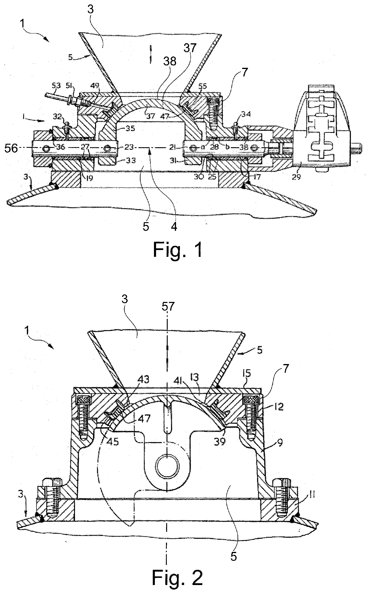
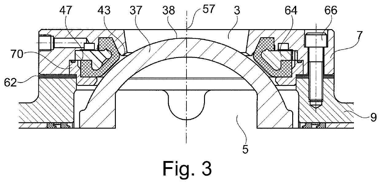
[0070]FIGS. 1, 2 and 3 show cross sections of a dome valve 1, having an inlet 3 and an outlet 5 defined by a body or housing 9, and an upper plate 7. In use, the outlet is typically at a lower pressure than the inlet. The inlet may for example be connected to a pressure vessel, and the outlet to a conveying pipeline.

[0071]Particulate material may be delivered using a flow of carrier gas, for example air, from the inlet 3 to the outlet 5, via a fluid passage indicated generally as 4.

[0072]In the embodiment shown, the body 9 is bolted at its outlet end to a flange 11 at the inlet to a conveying pipeline. Other connections may be used, such as a tri-clover fitting or the like. At its inlet end, the body 9 is similarly coupled to the outlet of a pressure vessel or hopper.

[0073]As seen best in FIG. 1, the valve 1 includes diametrically opposite disposed bearing arrangements 17 and 19 around a drive shaft 21 and a pivot shaft 23 respectively.

[0074]Drive shaft 21 extends outwardly beyond b...


PUM


Abstract

A valve with a valve upper plate defining an inlet, a valve body defining an outlet, and a fluid passage. A closure member is disposed in the fluid passage between the inlet and the outlet and has a convex sealing surface and is rotatable between a closed position in which the closure member extends across the fluid passage with the convex sealing surface oriented towards the inlet and an open position in which fluid is able to flow through the fluid passage from the inlet to the outlet. A resilient sealing ring, when the closure member is in the closed position, is moveable between a first configuration in which the sealing ring forms a seal around a circumference of the convex sealing surface and a second configuration in which the valve comprises a circumferential gap between the convex sealing surface and the sealing ring.

Description

[0001]This nonprovisional application is a continuation of International Application No. PCT / EP2020 / 060117, which was filed on Apr. 9, 2020, and which claims priority to Great Britain Patent Application No. 1905804.9, which was filed in Great Britain on Apr. 25, 2019, and which are both herein incorporated by reference.BACKGROUND OF THE INVENTIONField of the Invention[0002]The present invention relates to a valve and in particular to a valve for use in pneumatic conveying of particulate material.Description of the Background Art[0003]Pneumatic conveying by pressure or vacuum are techniques employed to transport particulate materials along a pipeline. These techniques are typically employed to 10 transport materials over distances typically in the range from 10 m to 500 m, and in some cases even further. Pneumatic conveying avoids the need for the use of conveyor belts or the like, which can be bulky and costly to maintain.[0004]Pneumatic conveying techniques are particularly useful ...

Claims


Application Information

Patent Timeline
IPC IPC(8): F16K3/32F16K3/24F16K27/04B65G53/46
CPCF16K3/32F16K3/243F16K31/041B65G53/4658F16K27/041F16K5/201F16K27/067F16K3/24F16K5/06B65G2201/042
Inventor NEWTON
Owner SCHENCK PROCESS EURO GMBH
Why Eureka
Try Eureka