
Integrated substrate structure, electronic assembly, and manufacturing method thereof

Pending Publication Date: 2022-02-03
HU DYI CHUNG
View PDF7 Cites 0 Cited by
  • Summary
  • Abstract
  • Description
  • Claims
  • Application Information

AI Technical Summary

Benefits of technology

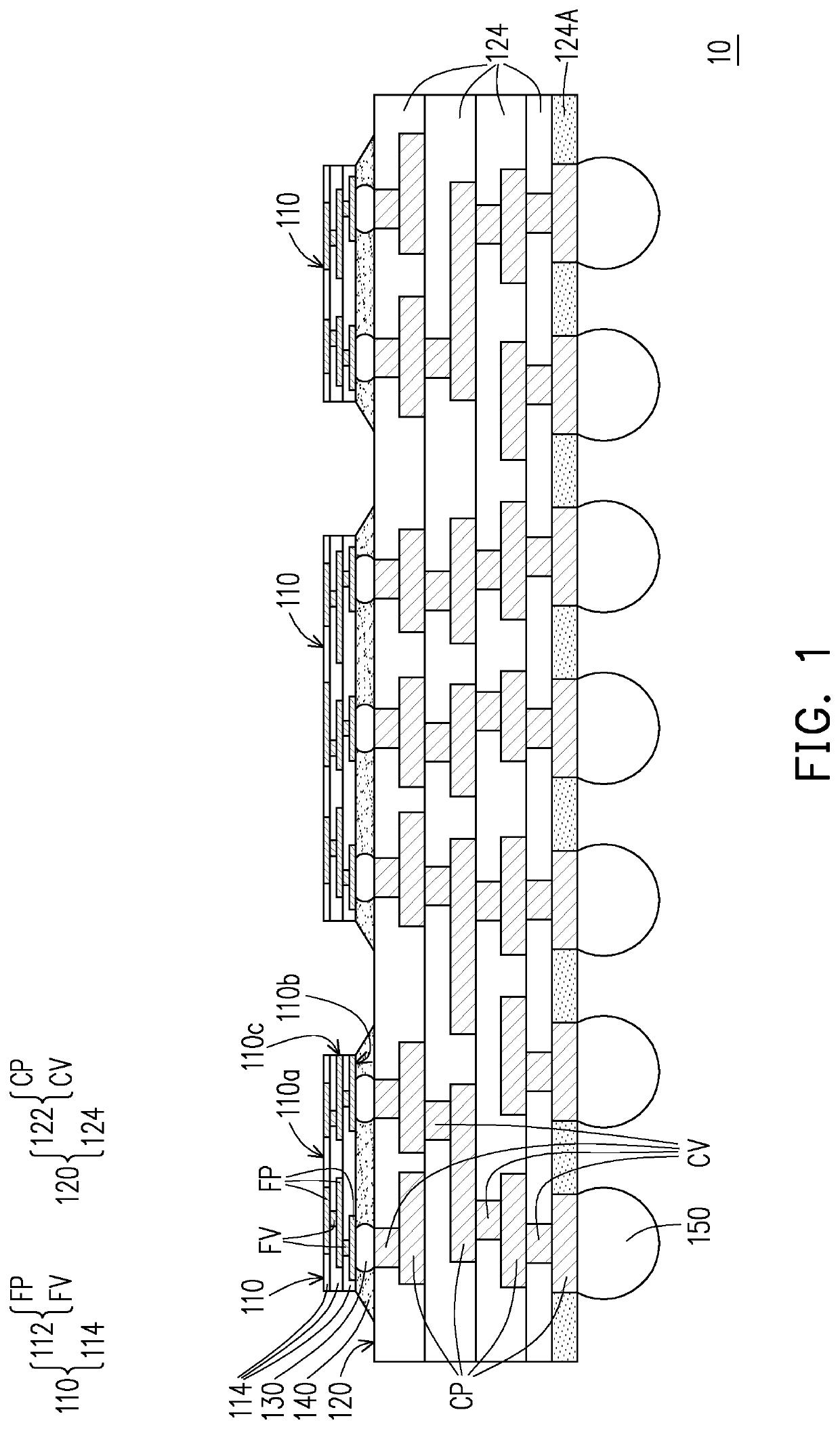
The patent text describes an integrated substrate structure that includes a coarse redistribution structure and fine redistribution segments mounted on it. These fine redistribution segments have fine pitches to meet the requirements of various chips. By embedding the chips between the fine redistribution segments and the coarse redistribution structure, the signal transmission path between them is shorter, which improves performance. The fine redistribution segments are also positioned on the coarse redistribution structure, which makes it easier to interconnect them. The overall mechanical strength of the structure is improved by encapsulating the fine redistribution segments with insulating segments. This embedded chip design enhances the functionality of the integrated substrate structure.

Problems solved by technology

However, the large sized substrate is either not readily manufactured or would require a specialized process which will significantly increase costs and likely lower yield.
These trends are leading to an increase in the power dissipation requirements of IC structure.

Method used


Image

  • Integrated substrate structure, electronic assembly, and manufacturing method thereof
  • Integrated substrate structure, electronic assembly, and manufacturing method thereof
  • Integrated substrate structure, electronic assembly, and manufacturing method thereof

Examples


Embodiment Construction

[0026]Reference will now be made in detail to the present preferred embodiments of the invention, examples of which are illustrated in the accompanying drawings. Wherever possible, the same reference numbers are used in the drawings and the description to refer to the same or like parts.

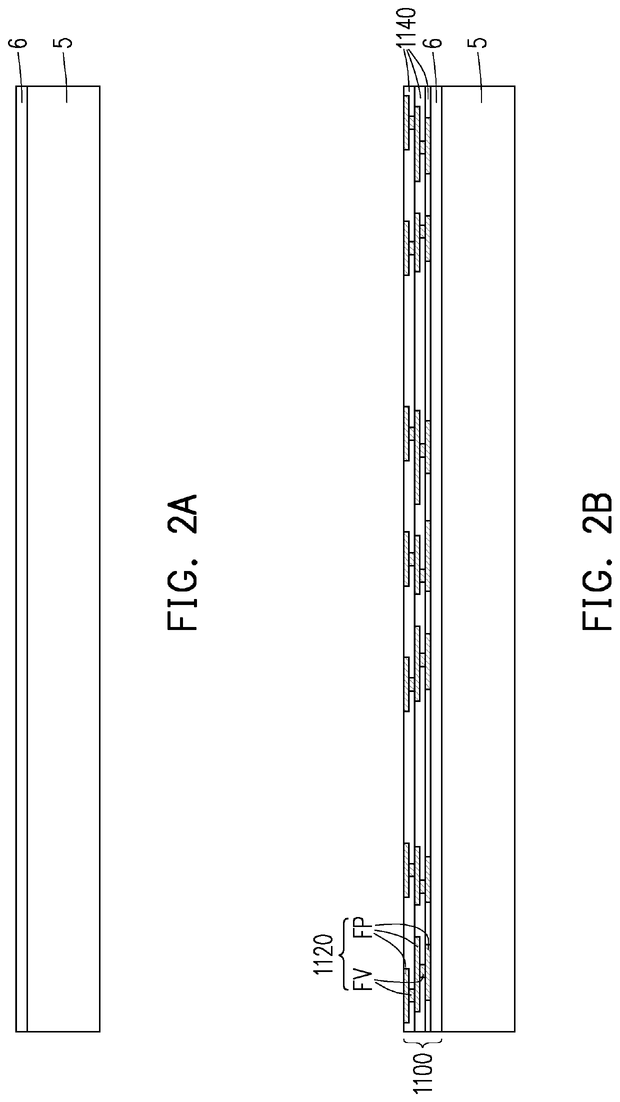
[0027]FIG. 1 is a schematic cross-sectional view of an integrated substrate structure in accordance with some embodiments. Referring to FIG. 1, an integrated substrate structure 10 includes a plurality of fine redistribution segments 110 mounted on a coarse redistribution structure 120. The size of the integrated substrate structure 10 may be large enough so that many chips (not shown) may be integrated simultaneously on the integrated substrate structure 10 through the fine redistribution segments 110. In some embodiments, the size of the integrated substrate structure 10 is about 80 mm×80 mm, 100 mm×100 mm, or even beyond this. Compared to a conventional substrate, the integrated substrate structur...


PUM


Abstract

An integrated substrate, an electronic assembly, and manufacturing methods thereof are provided. The integrated substrate structure includes a coarse redistribution structure, fine redistribution segments, and conductive connectors. The coarse redistribution structure includes a coarse dielectric layer and a coarse circuitry embedded therein. The fine redistribution segments disposed over the coarse redistribution structure and disposed side by side and apart from one another. The respective fine redistribution segment includes a fine dielectric layer thinner than the coarse dielectric layer, and a fine circuitry embedded in the fine dielectric layer. The fine circuitry includes a dimension and a pitch finer than those of the coarse circuitry, and a layout density of the fine circuitry is denser than that of the coarse circuitry. The conductive connectors are interposed between the coarse redistribution structure and the fine redistribution segments, and the coarse circuitry is electrically coupled to the fine circuitry through the conductive connectors.

Description

CROSS REFERENCE TO RELATED APPLICATION[0001]This application claims the priority benefit of U.S. provisional application Ser. No. 63 / 057,307, filed on Jul. 28, 2020. The entirety of the above-mentioned patent application is hereby incorporated by reference herein and made a part of specification.BACKGROUND OF THE INVENTION1. Field of the Invention[0002]The present invention relates to a semiconductor substrate, and more specifically relates to an integrated substrate structure with large format.2. Description of Related Art[0003]In packaging applications, multiple chips need to be placed on the substrate for performing various functions. This would require use of a larger substrate. However, the large sized substrate is either not readily manufactured or would require a specialized process which will significantly increase costs and likely lower yield. Therefore, a need exists to provide a large-format substrate for multiple chips mounted thereon.[0004]In addition, current trends in...

Claims


Application Information

Patent Timeline
IPC IPC(8): H01L23/498H01L23/00H01L25/10H01L23/367H01L21/48
CPCH01L23/49833H01L24/32H01L23/49811H01L25/105H01L23/367H01L2224/16227H01L21/486H01L24/83H01L21/4882H01L2224/32225H01L24/16H01L21/4853H01L23/49816H01L23/5383H01L23/5385H01L25/16H01L25/0657H01L2224/16225H01L2224/16145H01L2924/15322
Inventor HU, DYI-CHUNG
Owner HU DYI CHUNG
Learn More