Integrated illumination-detection flow cell for liquid chromatography

a flow cell and liquid chromatography technology, applied in the field of integrated illumination detection flow cells for liquid chromatography, can solve the problems of increasing both the time and the reducing the signal-to-noise ratio, and unsatisfactory thermal effects on samples, etc., to achieve the effect of increasing the size of the hplc system, reducing the time and cost of operating the hplc system, and substantial optical path length

Active Publication Date: 2022-02-03
EXCELITAS TECH
View PDF18 Cites 0 Cited by
  • Summary
  • Abstract
  • Description
  • Claims
  • Application Information

AI Technical Summary

Benefits of technology

The patent describes a new detector system for liquid chromatography that addresses issues of size, cost, and noise. The system includes a flow cell with a first and second optically transparent walls, multiple light sources controlled independently, and a detection chamber with a diffuse interior coating and photodetectors. The light sources, such as LEDs, are small and require no pre-warming, and the detection chamber is designed to collect and measure light from the flow cell with a high signal-to-noise ratio. The use of LEDs also reduces the cost of operation.

Problems solved by technology

Considerable heat is also generated by the above-mentioned light sources, which may lead to undesirable thermal effects on the sample inside the flow cell.
The light sources also have to be pre-warmed before use and typically have a limited life (for example, a tungsten lamp is typically replaced after ˜2000 hours of use), increasing both the time and the cost of operating the HPLC system.
The multiple optical elements may also contribute to additional noise generation, thereby diminishing the signal-to-noise ratio.

Method used


Image

  • Integrated illumination-detection flow cell for liquid chromatography
  • Integrated illumination-detection flow cell for liquid chromatography
  • Integrated illumination-detection flow cell for liquid chromatography

Examples


first embodiment

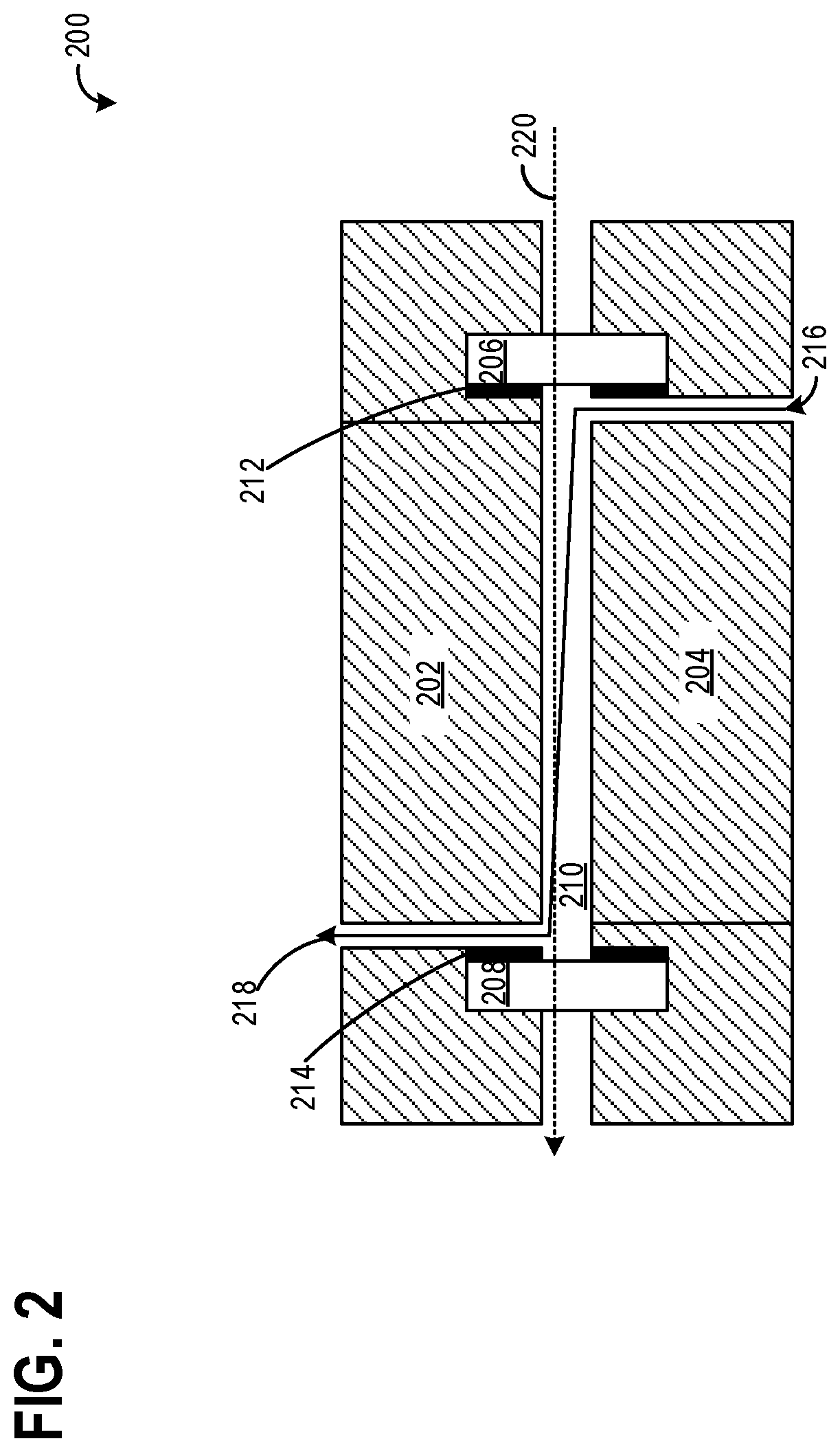
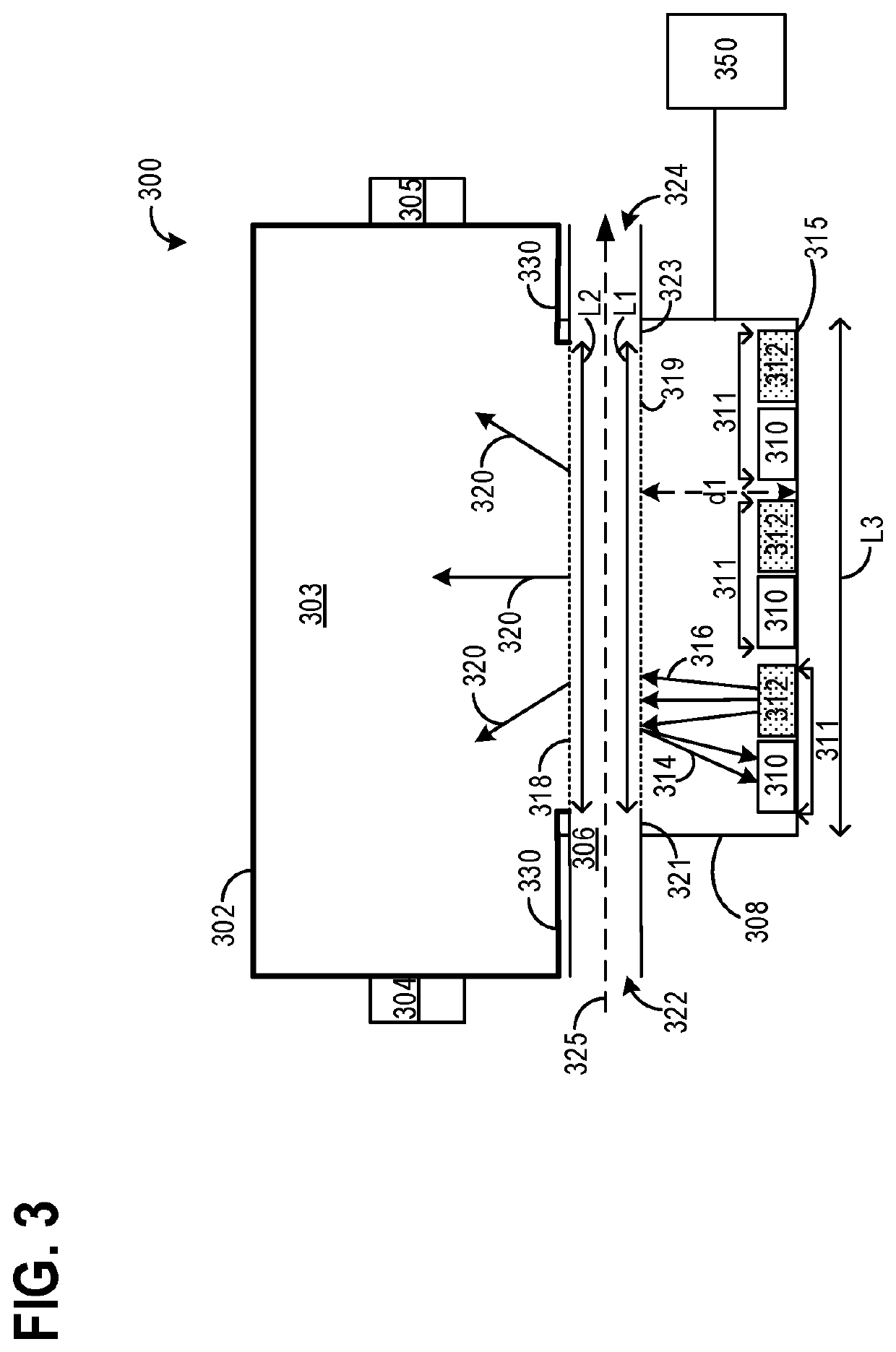
[0040]FIG. 3 illustrates an integrated illumination-detection flow cell 300. As an example, the integrated illumination-detection flow cell 300 may be included in a detection system of an HPLC system, such as detection system 160 of HPLC system 100 shown in FIG. 1. The integrated illumination-detection flow cell 300 may include a flow cell 308 with a flow channel 306, similar to the flow cell 200 illustrated in FIG. 2. The flow channel 306 may include an inlet 322 and an outlet 324, wherein a liquid sample may flow in through the inlet 322 along a path indicated by a dashed arrow 325 through the flow channel 306 and exit through the outlet 324. A flow rate of the liquid sample through the flow channel 306 may be regulated by a flow regulator (not shown) upstream of the inlet 322. The flow channel 306 may be at least partially inside the flow cell 308.

[0041]The flow cell 308 may include a plurality of diode pairs 311, each of the diode pairs 311 including a light source 312 and a pho...

second embodiment

[0050]FIG. 4 shows an integrated illumination-detection flow cell 400, which may be used in a liquid chromatography system (e.g., HPLC system 100 of FIG. 1). The integrated illumination-detection flow cell 400 may share common features and / or configurations as those already described above with reference to FIG. 3. Components previously introduced in FIG. 3 are numbered similarly and not reintroduced.

[0051]The configuration of the flow channel 306 along the flow cell 308 in the integrated illumination-detection flow cell 400 is the same as described above with reference to FIG. 3, except for an optical element between each light source 312 and the first optically transparent wall 319 of the flow channel 306. The flow cell 308 includes the plurality of diode pairs 311 along the bottom surface 315, wherein each of the diode pairs includes the light source 312 and the reference diode 310. Light emitted from each light source 312, which may be an LED emitting light of specific wavelengt...


PUM


Abstract

A liquid chromatography flow cell including an integrated light source and an integrated detection chamber. The integrated light source includes a plurality of light emitting diodes (LEDs), wherein each LED emits light of a specific wavelength. The light emitted from the integrated light source is directed to pass through a sample in a flow chamber of the flow cell without any optical conditioning, and the light not absorbed by the sample flows out of the flow chamber directly into the integrated detection chamber, where an intensity of the unabsorbed light is measured by detectors coupled to the integrated chamber.

Description

CROSS REFERENCE TO RELATED APPLICATIONS[0001]The present application claims priority to U.S. Provisional Application No. 62 / 462,786, entitled “INTEGRATED ILLUMINATION-DETECTION FLOW CELL FOR LIQUID CHROMATOGRAPHY,” and filed on Feb. 23, 2017, the entire contents of which are hereby incorporated by reference in their entirety for all purposes.BACKGROUND AND SUMMARY[0002]Conventional liquid chromatography systems; such as high-performance liquid chromatography (HPLC), two-dimensional HPLC, and ultra-high performance liquid chromatography (UHPLC), operate on the principle of exposing a sample to a particular wavelength of light to determine physical properties of the sample. Light emitted from a light source is optically transmitted through a flow cell of the liquid chromatography system. The light transmitted through the flow cell may be partially to fully absorbed by the sample inside the flow cell. Any unabsorbed light may scatter through the sample and is transmitted to a detection...

Claims


Application Information

Patent Timeline
Patent Type & Authority Applications(United States)
IPC IPC(8): G01N30/74G01N21/59G01N21/05G01N21/25G01N21/31
CPCG01N30/74G01N21/59G01N2030/027G01N21/255G01N21/31G01N21/05G01N2201/0627
Inventor ELIASON, GARTHKAIN, PATRICKFREITAG, JOHN CHRISTOPHERCHILDERS, DOUGPASQUANTONIO, JAY
Owner EXCELITAS TECH
Why Eureka
Try Eureka