Intertwined coil heat exchanger

a heat exchanger and intertwined coil technology, applied in lighting and heating apparatus, supercritical condition processes, bulk chemical production, etc., can solve the problems of amplification of the dean vortex, increase in the turbulence of the fluid passing through the coil, etc., to achieve maximum interweaving of the coil, increase the turbulence of the fluid, and the transfer coefficient (h) to be higher.

Pending Publication Date: 2022-02-03
AQUARDEN TECH
View PDF2 Cites 0 Cited by
  • Summary
  • Abstract
  • Description
  • Claims
  • Application Information

AI Technical Summary

Benefits of technology

This patent describes a new heat exchanger design for a supercritical water oxidation reactor that solves problems with previous designs. The heat exchanger has multiple coils that are intertwined with each other, which maximizes heat transfer and ensures consistent fluid flow through each coil. The coils have unique center paths that are represented as both helices, which results in a higher transfer coefficient and amplifies the Dean vortex. This design ensures efficient energy distribution and maintenance of optimal flow pattern, which makes it suitable for efficient salt extraction from supercritical fluid.

Problems solved by technology

To express this conceptually, the helixes are occurring on two cumulative levels, with the first level being the helical coils and the second level being the helical centre paths or axes of the coils, resulting in amplification of the Dean vortex and an increase in turbulence of the fluid passing through the coils.

Method used


Image

  • Intertwined coil heat exchanger
  • Intertwined coil heat exchanger
  • Intertwined coil heat exchanger

Examples


Embodiment Construction

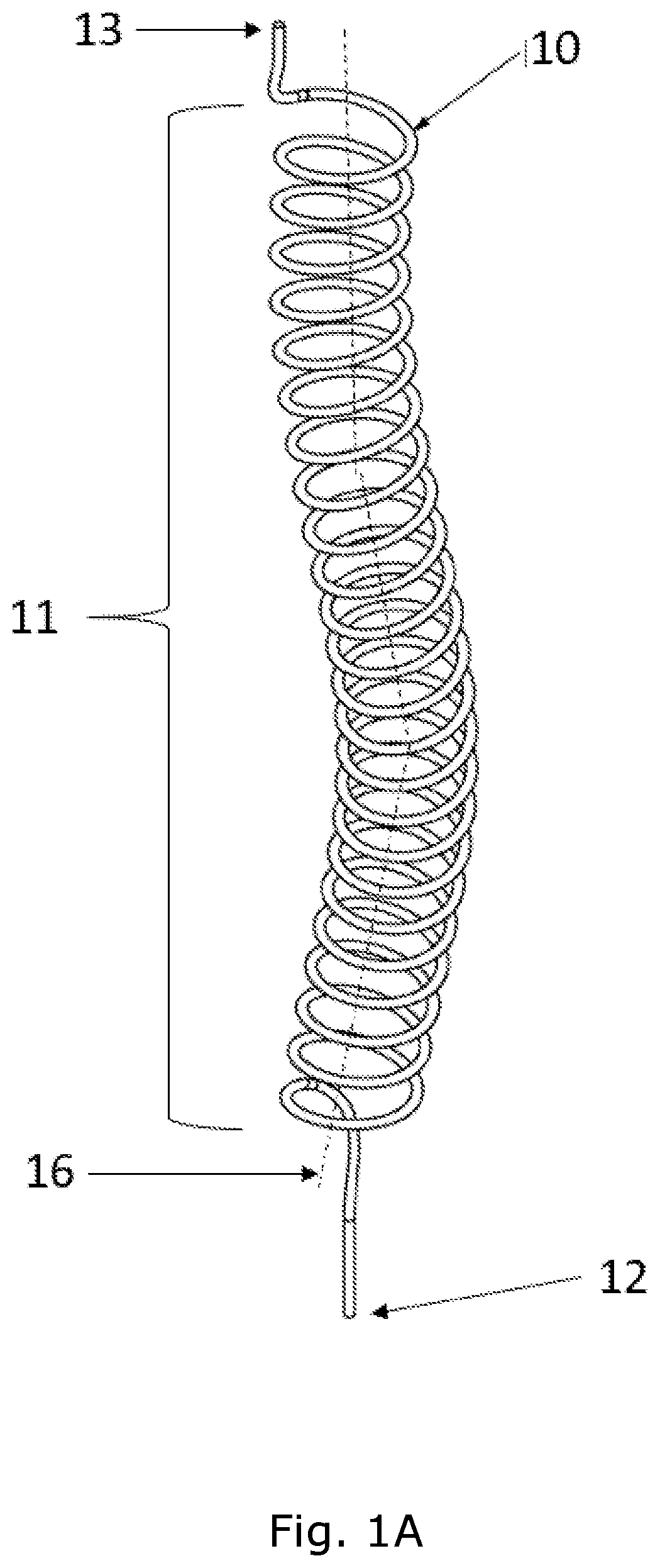
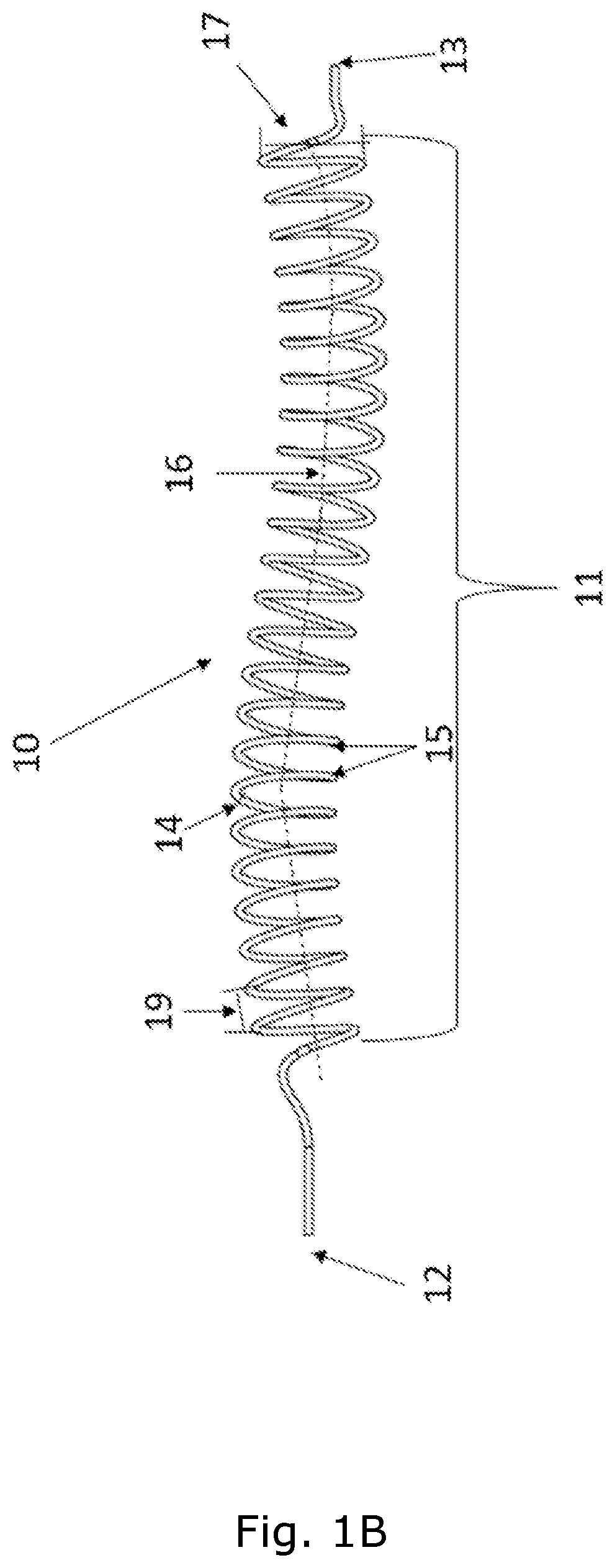
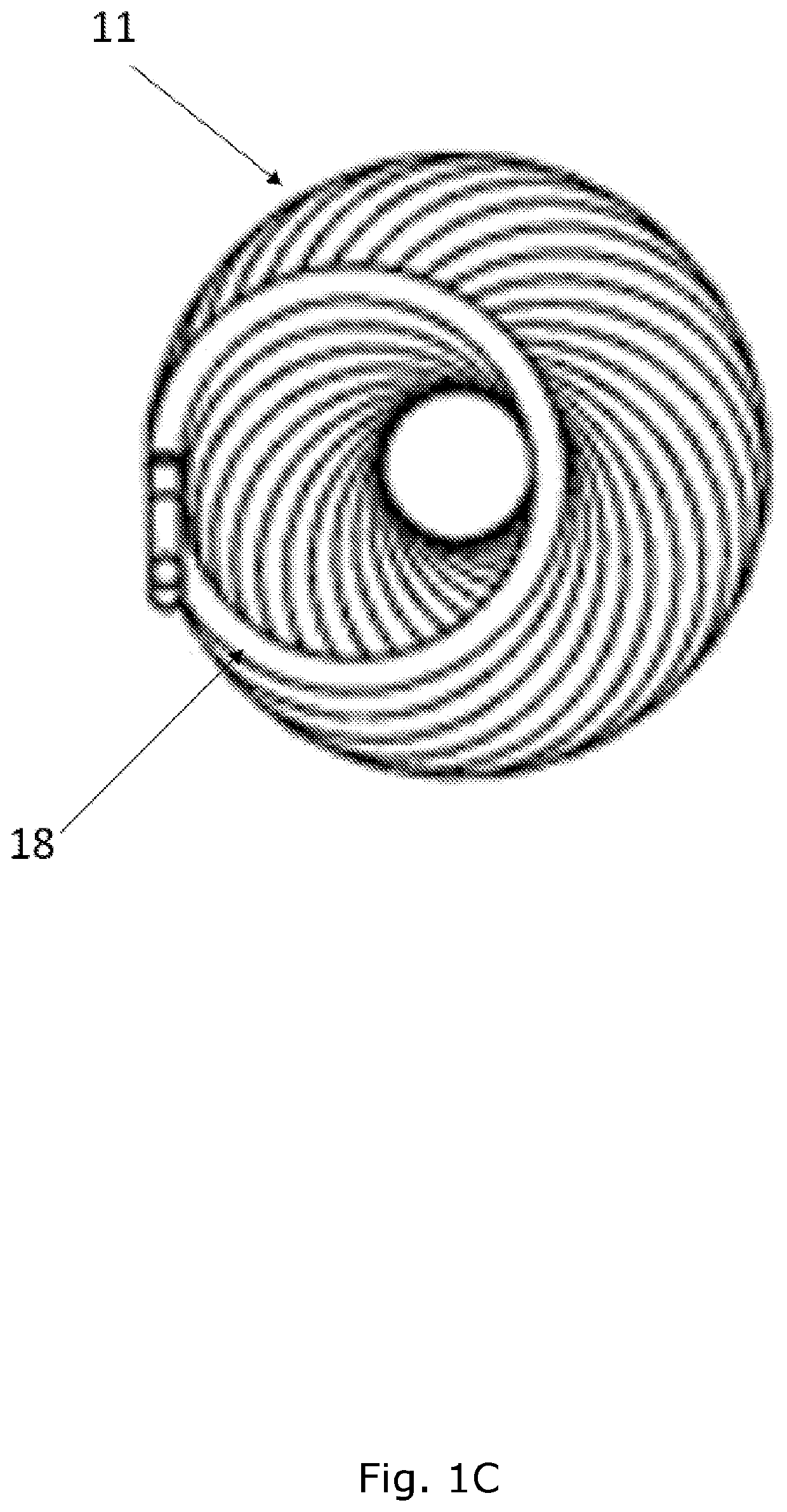
[0067]Reference is made to FIGS. 1A, 1B and 1C showing vertical, horizontal, and top views respectively, of a single tubular fluid channel 10, isolated from an exemplary heat exchanger of the present invention, which comprises at least two tubular fluid channels. The single tubular fluid channel 10 may be isolated from the exemplary heat exchanger according to FIGS. 2A-2C, or from the exemplary heat exchanger according to FIGS. 3A-3D, which will be described further in accordance with these drawings herein below. Due to the complexity of the structure of the heat exchanger, it may be preferable to first study the structure of an isolated single tubular fluid channel. In this exemplary drawing, the tubular fluid channel 10 is formed as a helical coil 11 over approximately eighty percent of its length. In alternative embodiments, the tubular fluid channel 10 is preferably formed as a helical or non-helical coil over at least sixty percent of its length to optimize the coil surface are...


PUM


Abstract

The present invention relates to the field of heat exchangers, especially those having a plurality of tubular fluid channels formed as intertwined coils, with each of the centre paths of the coils forming a helix, and to a reactor for supercritical water oxidation comprising such a heat exchanger.

Description

FIELD OF THE INVENTION[0001]The present invention relates to the field of heat exchangers, especially those having a plurality of tubular fluid channels formed as intertwined coils, with each of the centre paths of the coils forming a helix, and to a reactor for supercritical water oxidation comprising such a heat exchanger.BACKGROUND OF THE INVENTION[0002]The mechanical structure of a heat exchanger is key to facilitating efficient heat redistribution, such as for recovering energy in a supercritical water oxidation reactor. The coiled tube heat exchanger offers unique advantages: simultaneous heat transfer between more than two streams, a large heat transfer area, and promotes flow turbulence for enhancing heat transfer. Therefore, coiled tube heat exchangers are one of the three classical heat exchangers, i.e. shell and tube, double pipe, and coiled tube, used for large scale liquefaction systems. Helical coils are used for various processes because they can accommodate a large h...

Claims


Application Information

Patent Timeline
Patent Type & Authority Applications(United States)
IPC IPC(8): F28D7/02B01J3/00B01J19/24F28D7/00
CPCF28D7/022B01J3/008B01J2219/00083F28D7/0083B01J19/2415F28D7/024Y02P20/54
Inventor CAI, ZHUOYANBAEKGAARD, JENS
Owner AQUARDEN TECH
Why Eureka
Try Eureka