
Liquefier tube for an additive manufacturing system

a technology of additive manufacturing and liquefier tube, which is applied in the direction of additive manufacturing apparatus, electrolytic process, application layer means, etc., can solve the problems of limiting the types of feed channel shapes that can be produced, prolonging the residence time affecting the production efficiency so as to prevent the formation of dead spots, and prevent the decomposition and charring of am feedstock material. , the effect o

Active Publication Date: 2022-02-03
BOND HIGH PERFORMANCE 3D TECH BV
View PDF3 Cites 0 Cited by
  • Summary
  • Abstract
  • Description
  • Claims
  • Application Information

AI Technical Summary

Benefits of technology

This design ensures minimal residence time for the AM feedstock material, preventing decomposition and clogging, while allowing for improved heat transfer and efficient melting, thus maintaining material quality and extending the lifespan of the liquefier tube.

Problems solved by technology

This production method may limit the types of shapes of the feed channel that can be produced.
Moreover, roughness of the inner surface of the feed channel, especially in the transitional portion, may lead to extended residence time of the AM feedstock material.
In such dead spots, residence time of the AM feedstock material may be too long, leading to decomposition of the AM feedstock material.
This decomposition may lead for certain polymers to charring and clotting and thereby formation of particles which may clog the outlet portion of the liquefier tube and contaminate the feedstock material deposited on the object to be created using AM.
This is especially troublesome for AM systems which are arranged for high precision.
Such AM systems have liquefier tubes which can be provided with narrow high precision orifices and are therefore more prone to clogging by particles in the AM feedstock material.
Furthermore, charring, clotting and particle forming may be troublesome while applying high performance AM feedstock materials.
Even when such decomposed materials pass through the orifice and are deposited on the 3D object to be created, such particles may degrade material characteristics and performance and lead to rejection of the 3D object after completion of the 3D printing process.

Method used


Image

  • Liquefier tube for an additive manufacturing system
  • Liquefier tube for an additive manufacturing system
  • Liquefier tube for an additive manufacturing system

Examples


Embodiment Construction

[0059]Embodiments of the invention will be elucidated in the description below with reference to the drawings.

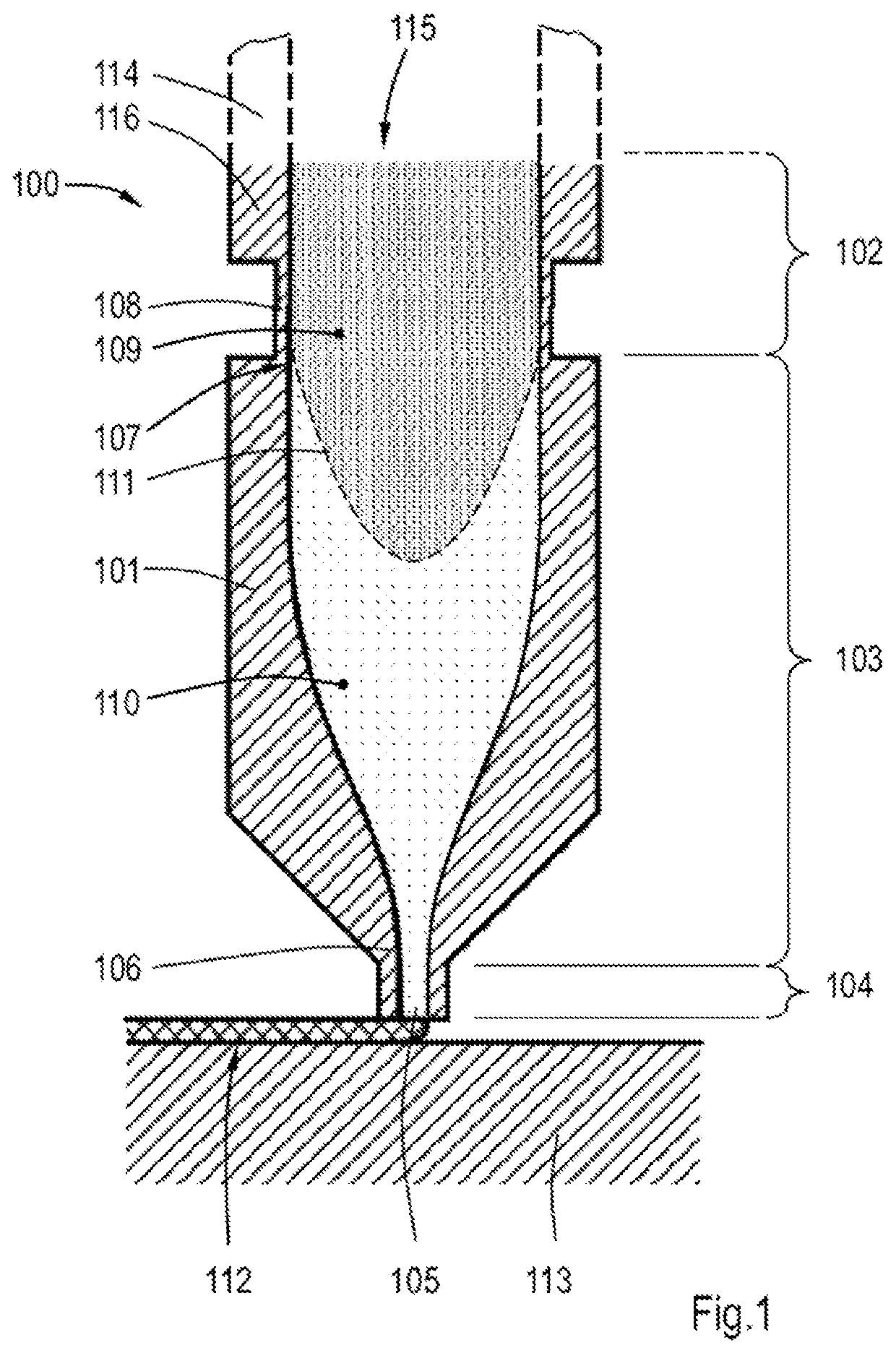
[0060]In FIG. 1 a liquefier tube 100 is shown having a liquefier body 101, wherein a feed channel 115 is created for feeding initially solid AM feedstock material 109, and molten AM feedstock material 110 towards an orifice 105. The feed channel 115 can be formed as a tubular passage through the liquefier body 101. The liquefier body 101 is preferably manufactured from a heat conductive material, such as a metal, and can be mounted in a heating system to melt the supplied solid AM feedstock material 109 into molten AM feedstock material 110. The phase transition between solid AM feedstock material 109 and molten AM feedstock material 110 is represented by dashed line 111. The molten AM feedstock material 110 can exit through orifice 105 of the feed channel 115. The liquefier tube 100 is preferably manufactured in one piece.

[0061]By three-dimensionally moving the liquefier tu...


PUM

PropertyMeasurementUnit
Raaaaaaaaaaa
Raaaaaaaaaaa
Raaaaaaaaaaa

Abstract

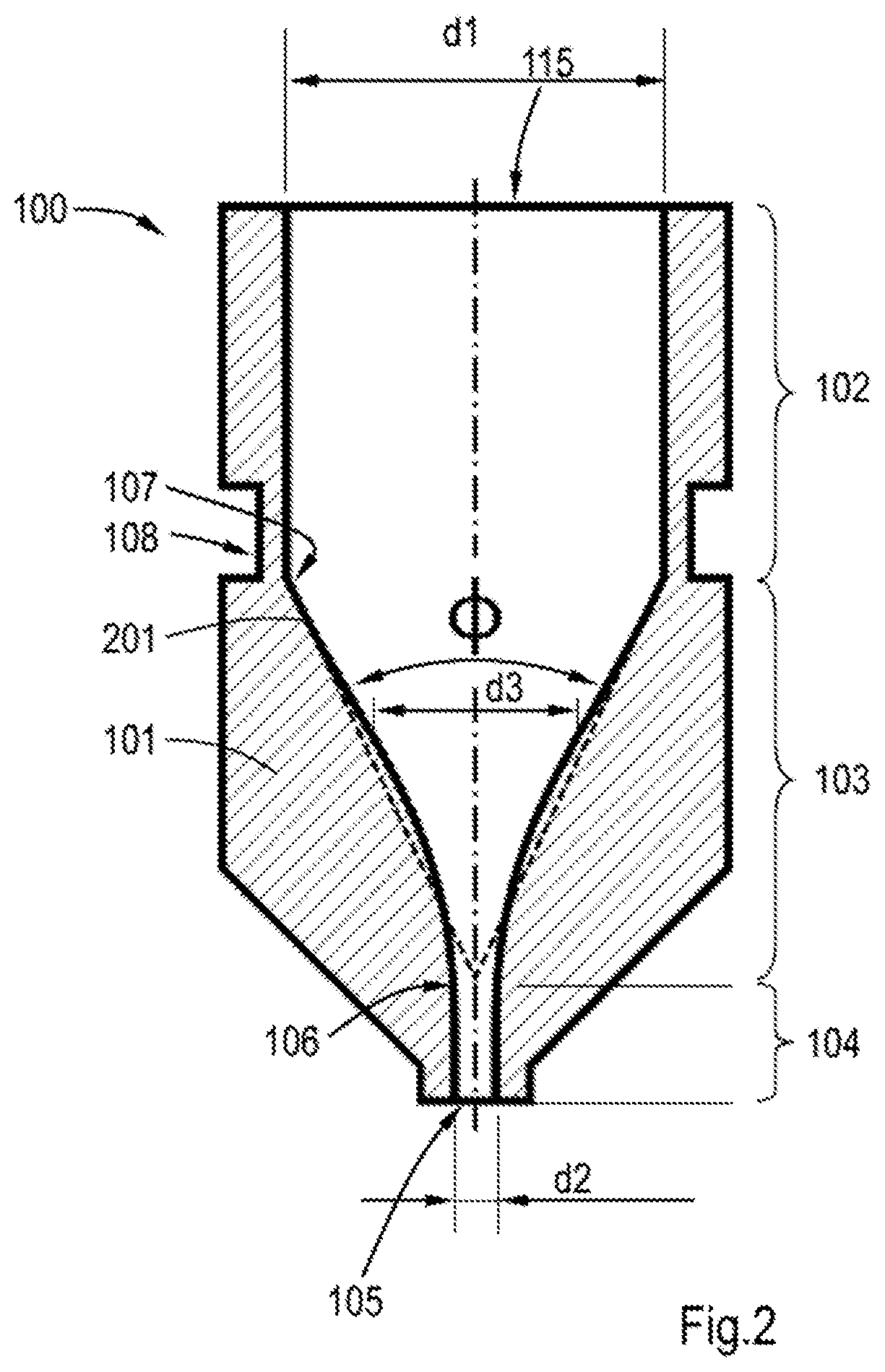
A liquefier tube for an additive manufacturing system, the liquefier tube including a body provided with a feed channel including a feeding portion having a first diameter, an outlet portion having a second diameter, the first diameter being larger than the second diameter, a transitional portion interconnecting the feeding portion and the outlet portion. The transitional portion has a monotonically decreasing third diameter from the feeding portion to the outlet portion and the third diameter as function of a longitudinal position of the feed channel in the transitional portion between the feeding portion and the outlet portion and at a transition between the transitional portion and the outlet portion is differentiable. Methods of manufacturing the liquefier tube.

Description

FIELD OF THE INVENTION[0001]The invention relates to a liquefier tube for an additive manufacturing (AM) system. The invention further relates to methods of manufacturing the liquefier tube.BACKGROUND OF THE INVENTION[0002]Liquefier tubes in AM systems are used to melt AM feedstock material to allow the feedstock material to be deposited in layers to manufacture three-dimensional (3D) objects to be created in accordance to electronic models which are used in the AM systems. AM feedstock material can comprise polymers which be advantageously used in AM systems for 3D modeling objects.[0003]Liquefier tubes can be attached to a three-dimensionally movable platform, also known in the art as printhead assembly, which may be further equipped with a supply of AM feedstock material and heaters to heat the liquefier tube to obtain a temperature appropriate for dispensing the AM material for depositing on the 3D object. The printhead assembly can be moved relative to the object in space to be...

Claims


Application Information

Patent Timeline
Patent Type & Authority Applications(United States)
IPC IPC(8): B29C64/209B29C48/02B29C48/05B29C48/30B29C48/92
CPCB29C64/209B29C48/02B33Y30/00B29C48/3001B29C48/92B29C48/05B29C48/25C25D1/02
Inventor BRUGGEMAN, ADRIANUSSPEELMAN, MARALDGROEN, KLAASWOLBERS, MARTIJN JOHANNESKUIT, KOENDERT HENDRIKEKKELENKAMP, ANTONIE EVERHARD
Owner BOND HIGH PERFORMANCE 3D TECH BV
Learn More